

Synchronous memory device with reduced power consumption
- Summary
- Abstract
- Description
- Claims
- Application Information
AI Technical Summary
Benefits of technology
Problems solved by technology
Method used
Image

Examples
Embodiment Construction
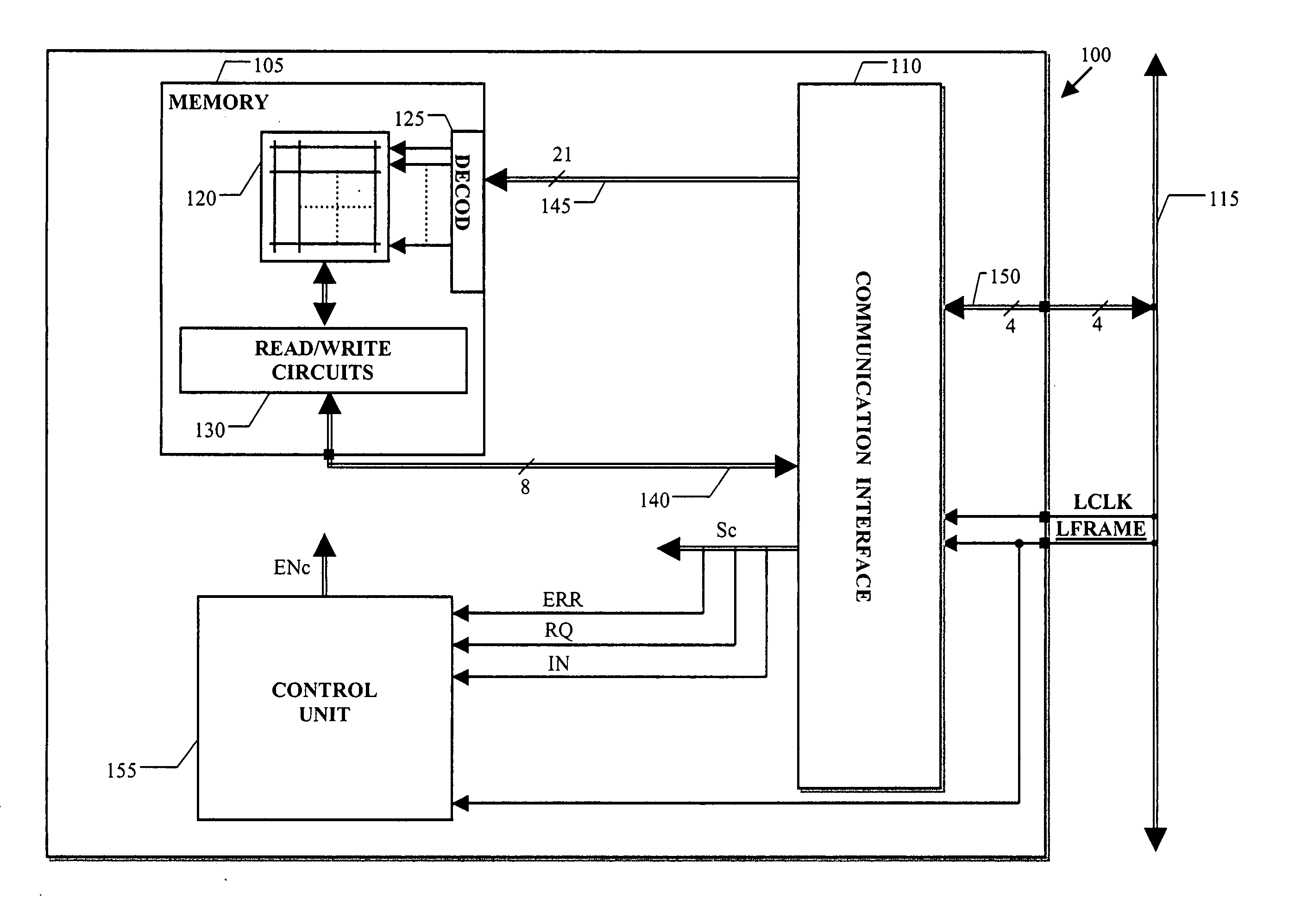
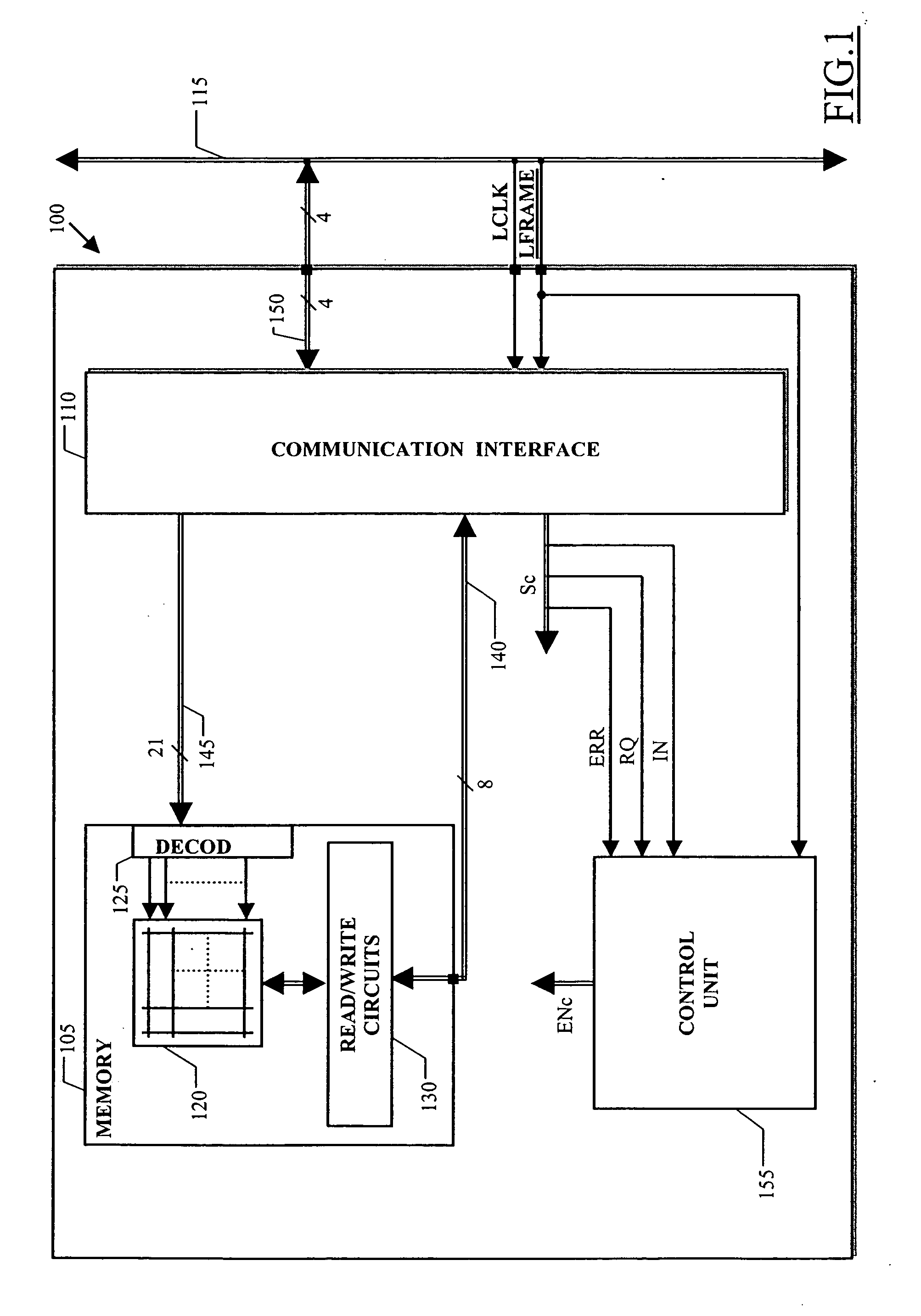
[0032] With reference particularly to FIG. 1, a functional block diagram is shown of an integrated device 100 according to an embodiment of the present invention. The integrated device 100 includes (preferably in a same chip of semiconductor material) a semiconductor memory 105 and a communication interface 110 adapted to interface the memory 105 with external devices (not shown in the figure) through a suitable external communication bus 115. Such external devices, for example, can include a microprocessor, a microcontroller, a digital signal processor (DSP) and similar.
[0033] The memory 105 is of the non-volatile type, particularly but not limitatively a flash EEPROM memory. The memory 105 includes a matrix 120 of memory cells (for example, made with floating gate MOS transistors). The memory 105 manages groups of bits in parallel, which define a word stored in a corresponding memory location. The memory locations are selectively accessed, for reading or for writing, by providing...
PUM
 Abstract
Description
Claims
Application Information