Light assembly for automotive lighting applications

a technology for automotive lighting and assembly, applied in the direction of lighting and heating apparatus, semiconductor devices for light sources, instruments, etc., can solve the problems that not all automotive applications, such as the stop function of tail lights, have been effectively produced, etc., to achieve efficient collection and redirection of light, reduce light scattering, and improve light collection and redirection efficiency

Inactive Publication Date: 2007-05-31
VARROC LIGHTING SYST SRO
View PDF99 Cites 23 Cited by
  • Summary
  • Abstract
  • Description
  • Claims
  • Application Information

AI Technical Summary

Benefits of technology

[0004] The present invention provides an automotive light assembly which produces numerous beam patterns meeting automotive requirements through the reduction of light scatter and efficient collection and redirection of light from a light source. The light assembly is arranged along a longitudinal axis, and generally comprises a light source and a light conducting body. The light source projects light laterally relative to the longitudinal axis. The light conducting body includes a hub and a plurality of fingers extending from the hub. The hub is positioned adjacent the light source and has a laterally facing surface receiving light from the light source. Each of the plurality of fingers extends laterally and longitudinally from the hub, and include a longitudinally facing surface for emitting the light passing through the plurality of fingers. By using a plurality of small individual fingers, large and bulky light pipes may be eliminated and the light collection and redirection efficiency improved.

Problems solved by technology

Unfortunately, not all automotive applications, such as the stop function of a tail light, have been effectively produced utilizing an LED light source and such reflectors, lenses or light pipes.

Method used


Image

  • Light assembly for automotive lighting applications
  • Light assembly for automotive lighting applications
  • Light assembly for automotive lighting applications

Examples


Embodiment Construction

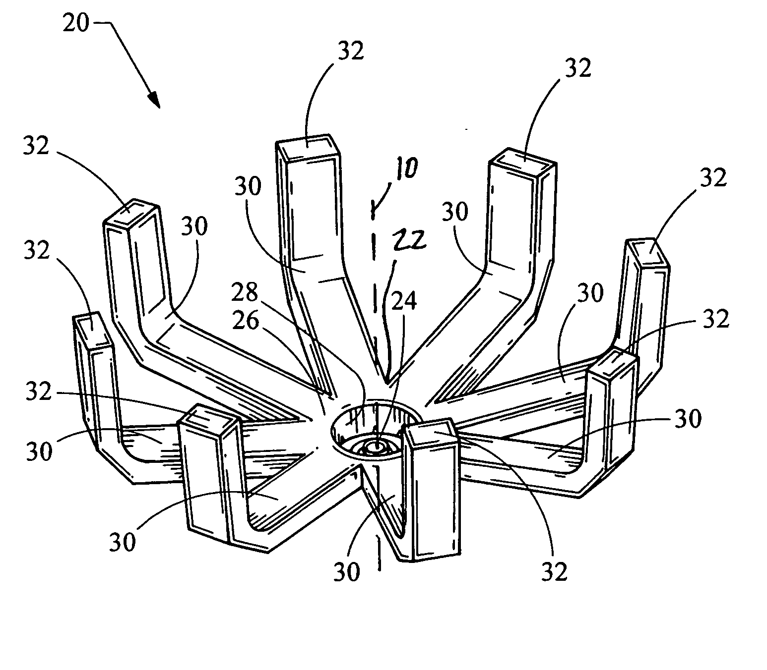
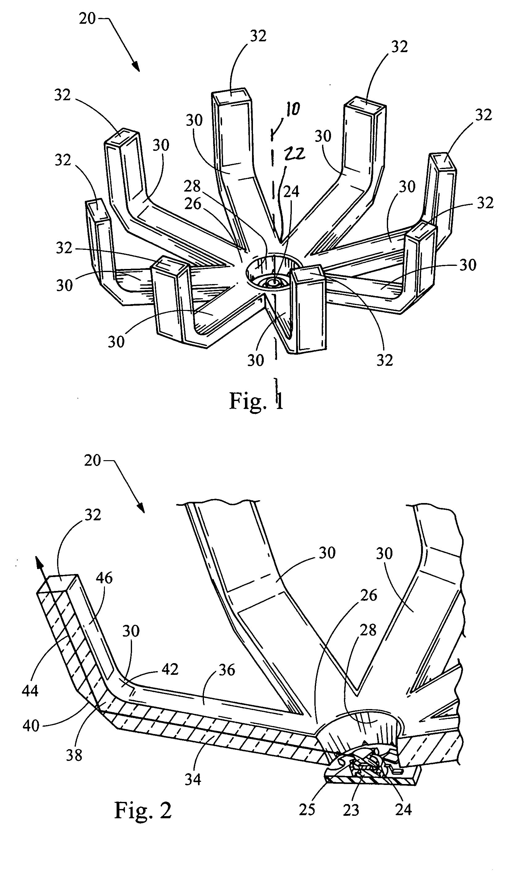
[0012] Turning now to the figures, FIG. 1 depicts a perspective view of an automotive light assembly 20 constructed in accordance with the teachings of the present invention. The light assembly 20 is generally arranged along a longitudinal axis 10, and includes a light conducting body 22 and a light source 24.

[0013] As best seen in the enlarged, partially cut-away view of FIG. 2, the light source 24 generally includes a light emitting diode (LED) 23 coupled with a near field lens 25 for redirecting the light laterally relative to the longitudinal axis 10. It will be recognized by those skilled in the art that various types of LED's or other light sources may be employed, and likewise various lenses, reflectors or other devices may be used to direct the light laterally. For example, numerous LED's are constructed to emit light to the side (i.e. laterally) thus obviating the need for a redirecting lens 25. Alternatively, a side-emitting, ring-shaped, near field lens may be built as a...


PUM


Abstract

An automotive light assembly produces numerous beam patterns meeting automotive requirements through the reduction of light scatter and collection and redirection in efficiencies. A light source projects light laterally, which is collected by a light conducting body having a hub and a plurality of fingers extending from the hub. By using a plurality of small individual fingers, large and bulky light pipes are eliminated and the light collection and redirection efficiency is improved.

Description

FIELD OF THE INVENTION [0001] The present invention relates generally to light assemblies for automotive applications, and more particularly relates to light assemblies employing light emitting diodes as light sources. [0002] Accordingly, there exists a need to provide an automotive lighting assembly capable of employing an LED light source to meet the special requirements of automotive lighting functions. BACKGROUND OF THE INVENTION [0003] Light emitting diodes (LED's) are fast becoming a preferable light source for automotive lighting applications, as they consume less power but provide light output which is acceptable for such applications. In order to employ LED's and automotive applications, high levels of efficiency must be obtained in both light collection as well as light distribution. Typically, reflectors or lenses or light pipes are utilized to collect and distribute the light for the particular lighting application. Unfortunately, not all automotive applications, such as...

Claims


Application Information

Patent Timeline
Patent Type & Authority Applications(United States)
IPC IPC(8): B60Q1/00
CPCB60Q1/2696B60Q3/004F21S48/215F21S48/2237F21S48/225F21S48/2262F21S48/2287F21S48/236F21V7/0091F21Y2101/02G02B6/0018G02B6/0021B60Q3/64F21Y2115/10F21S43/14F21S43/237F21S43/241F21S43/243F21S43/247F21S43/315
Inventor CHINNIAH, JEYACHANDRABOSESAYERS, EDWIN MITCHELL
Owner VARROC LIGHTING SYST SRO
Why Eureka
Try Eureka