Decoding apparatus and method utilized in an optical storage device

Active Publication Date: 2007-05-31
REALTEK SEMICON CORP
View PDF5 Cites 9 Cited by
  • Summary
  • Abstract
  • Description
  • Claims
  • Application Information

AI Technical Summary

Problems solved by technology

However, the RF signal may have mismatch problems due to interference caused by the system or the operating environment, such as the pick-up head

Method used


Image

  • Decoding apparatus and method utilized in an optical storage device
  • Decoding apparatus and method utilized in an optical storage device
  • Decoding apparatus and method utilized in an optical storage device

Examples


Embodiment Construction

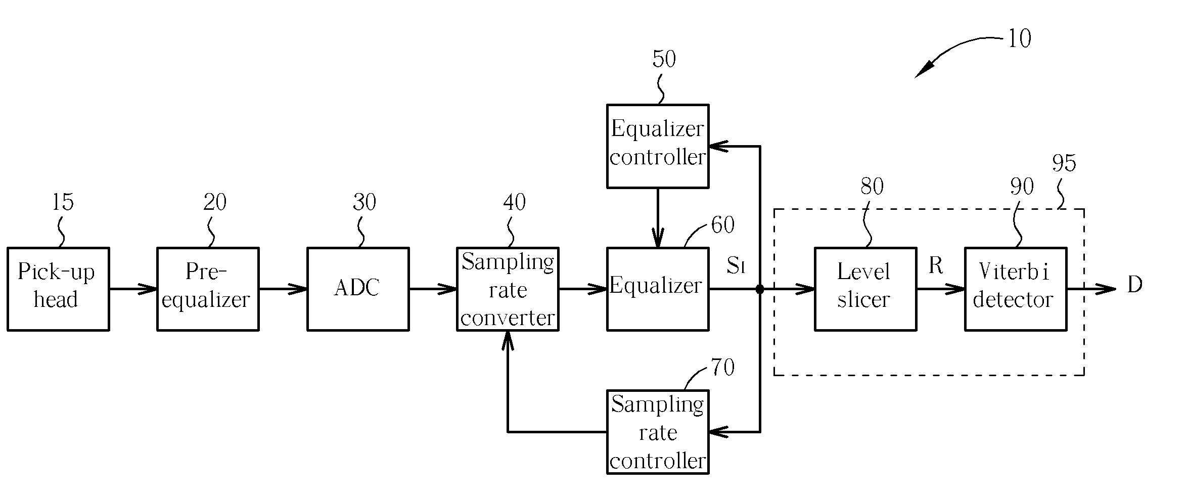
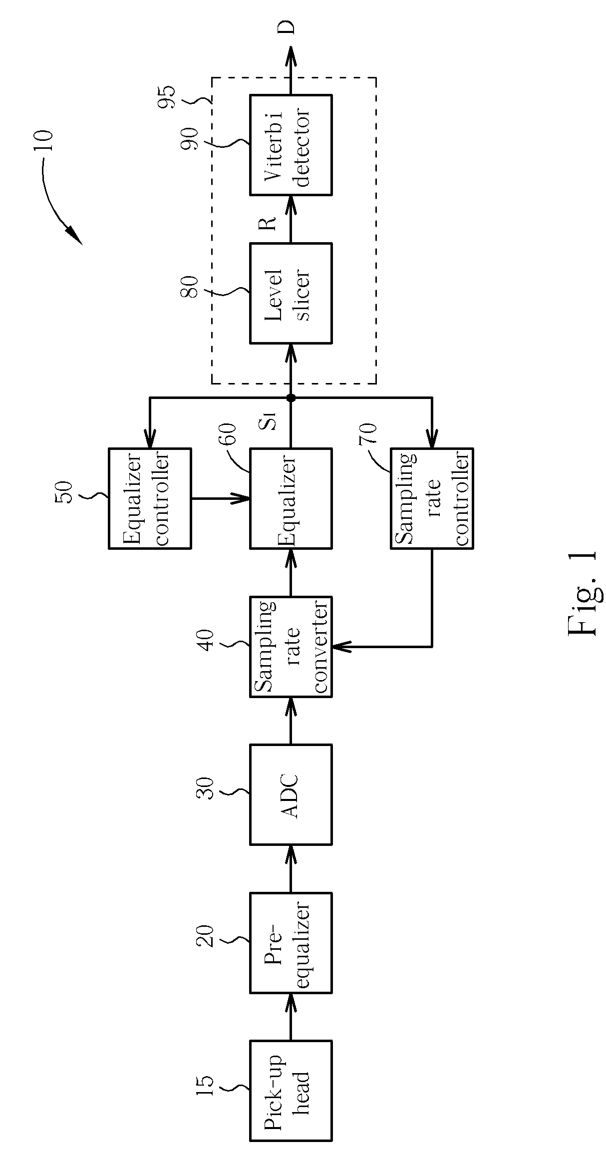
[0015] Please refer to FIG. 1, which shows a block diagram of a decoding apparatus 95 for use in an optical storage device 10 according to a first embodiment of the present invention. The optical storage device 10 comprises a pick-up head 15, a pre-equalizer 20, an ADC 30, a sampling rate converter 40, an equalizer 60, an equalizer controller 50, a sampling rate controller 70, and the decoding apparatus 95. As illustrated in FIG. 1, the decoding apparatus 95 comprises a level slicer 80 and a Viterbi detector 90. The pick-up head 15 emits a laser beam to read data recorded on an optical disc and converts the reflected laser beam into an analog signal, i.e., the RF signal described previously. The analog signal is amplified by the pre-equalizer 20 and then converted into a digital signal by the ADC 30. Since the sampling rate adopted by the ADC 30 to perform the analog-to-digital conversion differs from the channel bit rate, the digital signal generated by the ADC 30 needs to be adjus...


PUM


Abstract

A decoding apparatuses and a method utilized in an optical storage device are disclosed. The decoding apparatus includes: a level slicer for setting a plurality of adjustable boundary values to distinguish a plurality of signal regions, and outputting a set of state values in accordance with signal regions corresponding to an input value; and a Viterbi detector coupled to the level slicer for decoding a transmission data according to the state value.

Description

BACKGROUND OF THE INVENTION [0001] 1. Field of the Invention [0002] The present disclosure relates to decoding apparatuses and related methods, and more particularly, to decoding apparatuses and methods that correct the non-linear effect by adjusting the boundaries of signal regions of a level slicer. [0003] 2. Description of the Prior Art [0004] In an optical storage system, such as a conventional optical disc drive (e.g., VCD player or DVD+ / -R disc drive), data are decoded from the conventional RF signal retrieved from an optical disc. However, the RF signal may have mismatch problems due to interference caused by the system or the operating environment, such as the pick-up head drift or electronic noise, and which results in nonlinear distortion to the decoded signal so the decoded digital data stream is prone to errors. The conventional decoding operation decodes data by using a Viterbi detector. For example, the U.S. Pat. No. 6,754,160 utilizes a DC offset compensation control ...

Claims


Application Information

Patent Timeline
IPC IPC(8): G11B20/10
CPCG11B20/10009G11B20/10046
Inventor HE, WEI-HUNG
Owner REALTEK SEMICON CORP
Why Eureka
Try Eureka