
Performance testing apparatus for heat pipes

a technology of performance testing and heat pipes, which is applied in the direction of heat measurement, material heat development, instruments, etc., can solve the problems of inability to achieve sufficient intimate contact between the heat pipe and the heat pipe, inability to obtain rth and qmax by this test, and inability to accurately reflect the performance of the heat pip

Inactive Publication Date: 2007-05-31
HON HAI PRECISION IND CO LTD
View PDF9 Cites 9 Cited by
  • Summary
  • Abstract
  • Description
  • Claims
  • Application Information

AI Technical Summary

Benefits of technology

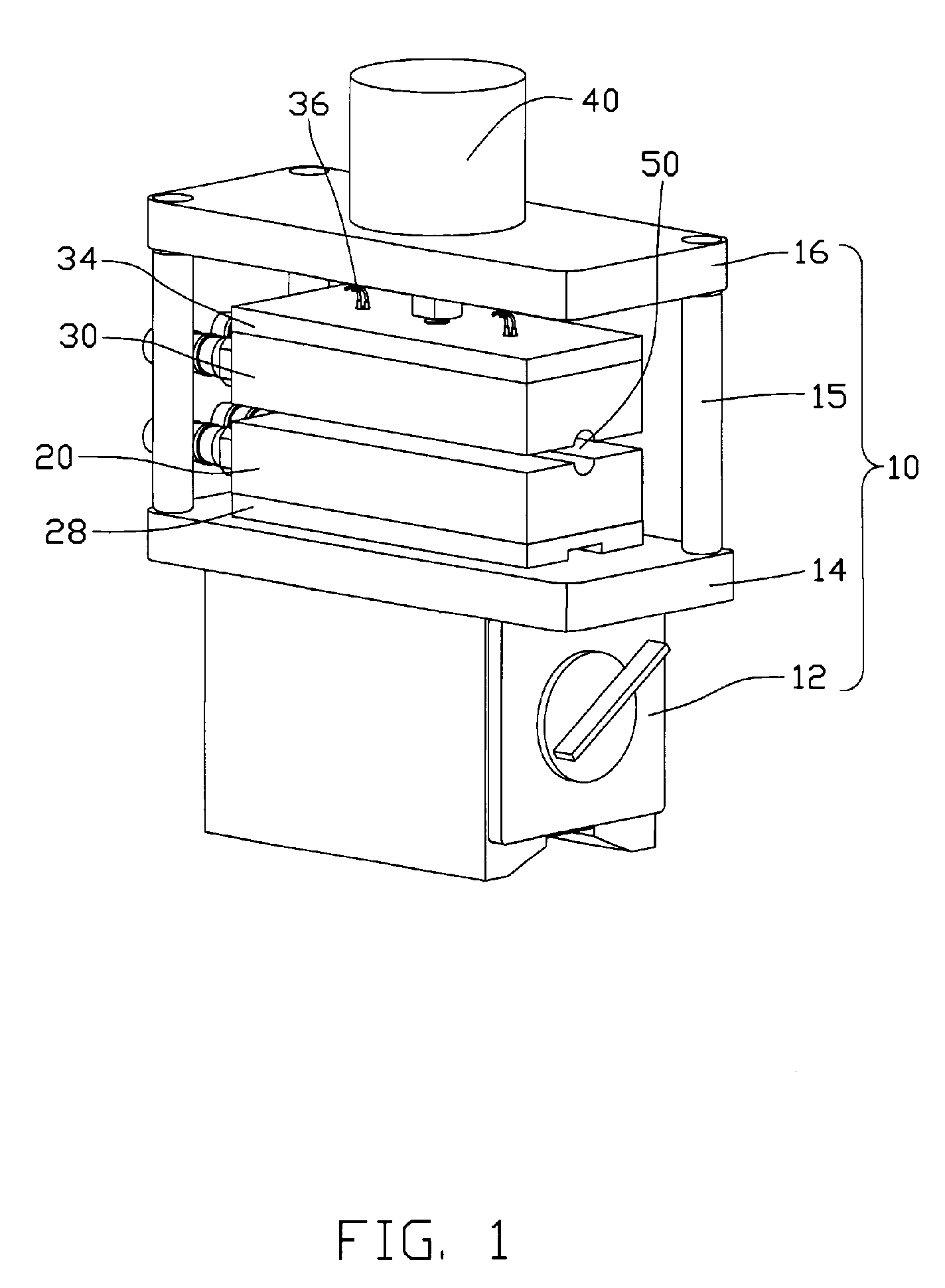
[0013]FIG. 1 is an assembled view of a performance testing apparatus for heat pipes in accordance with a preferred embodiment of the present invention;
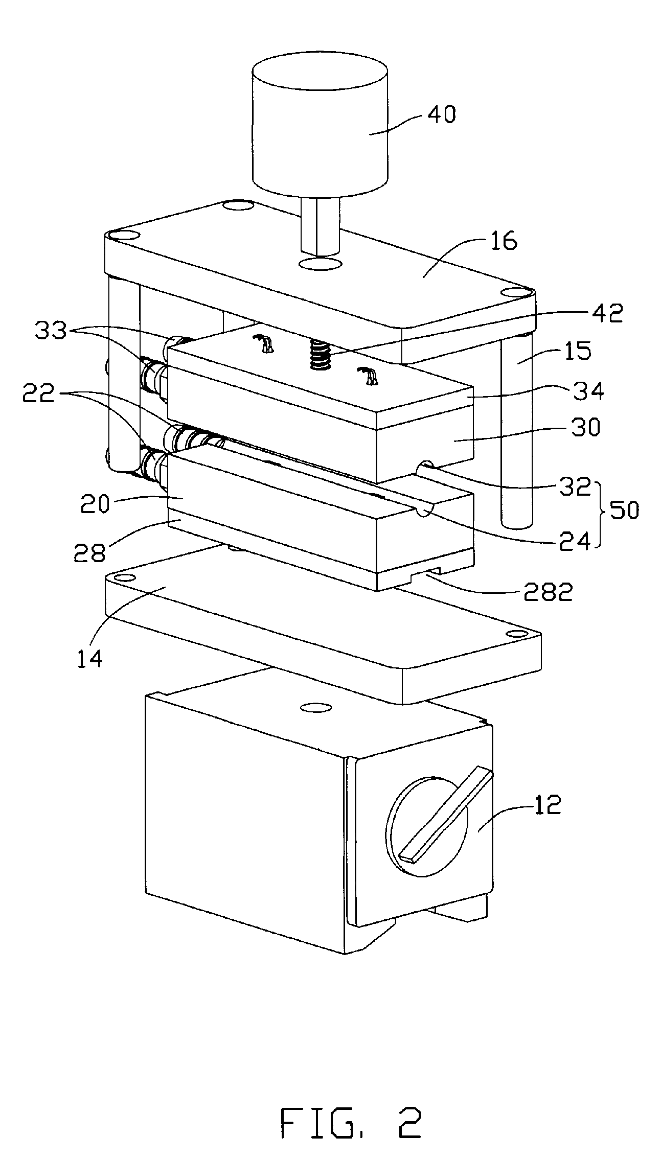
[0010] A performance testing apparatus for a heat pipe in accordance with a preferred embodiment of the present invention comprises an immovable portion having a cooling structure defined therein for removing heat from a condensing section of a heat pipe requiring testing. A movable portion is capable of moving relative to the immovable portion and also has a cooling structure defined therein for cooling the heat pipe. A receiving structure is defined between the immovable portion and the movable portion for receiving the condensing section of the heat pipe therein. At least one temperature sensor is attached to at least one of the immovable portion and the movable portion. The at least one temperature sensor has a portion thereof exposed in the receiving structure for thermally contacting the condensing section of the heat pipe in the receiving structure to detect a temperature of the heat pipe. The movable portion is driven by a driving device such as a step motor to move towards or away from the immovable portion. A spring coil is compressed to exert a force on the at least one temperature sensor towards an intimate contact with the condensing section of the heat pipe.
[0010] A performance testing apparatus for a heat pipe in accordance with a preferred embodiment of the present invention comprises an immovable portion having a cooling structure defined therein for removing heat from a condensing section of a heat pipe requiring testing. A movable portion is capable of moving relative to the immovable portion and also has a cooling structure defined therein for cooling the heat pipe. A receiving structure is defined between the immovable portion and the movable portion for receiving the condensing section of the heat pipe therein. At least one temperature sensor is attached to at least one of the immovable portion and the movable portion. The at least one temperature sensor has a portion thereof exposed in the receiving structure for thermally contacting the condensing section of the heat pipe in the receiving structure to detect a temperature of the heat pipe. The movable portion is driven by a driving device such as a step motor to move towards or away from the immovable portion. A spring coil is compressed to exert a force on the at least one temperature sensor towards an intimate contact with the condensing section of the heat pipe.

Problems solved by technology

However, Rth and Qmax can not be obtained by this test, and the performance of the heat pipe can not be reflected exactly by this test.
However, in the test, the conventional testing apparatus has the following drawbacks: a) it is difficult to accurately determine lengths of the evaporating section 2a and the condensing section 2b which are important factors in determining the performance of the heat pipe 2; b) heat transference and temperature measurement may easily be effected by environmental conditions; and, c) it is difficult to achieve sufficiently intimate contact between the heat pipe and the heat source and between the heat pipe and the heat sink, which results in uneven performance test results of the heat pipe.
Furthermore, due to awkward and laborious assembly and disassembly in the test, the testing apparatus can be only used in the laboratory, and can not be used in the mass production of heat pipes.

Method used


Image

  • Performance testing apparatus for heat pipes
  • Performance testing apparatus for heat pipes
  • Performance testing apparatus for heat pipes

Examples


first embodiment

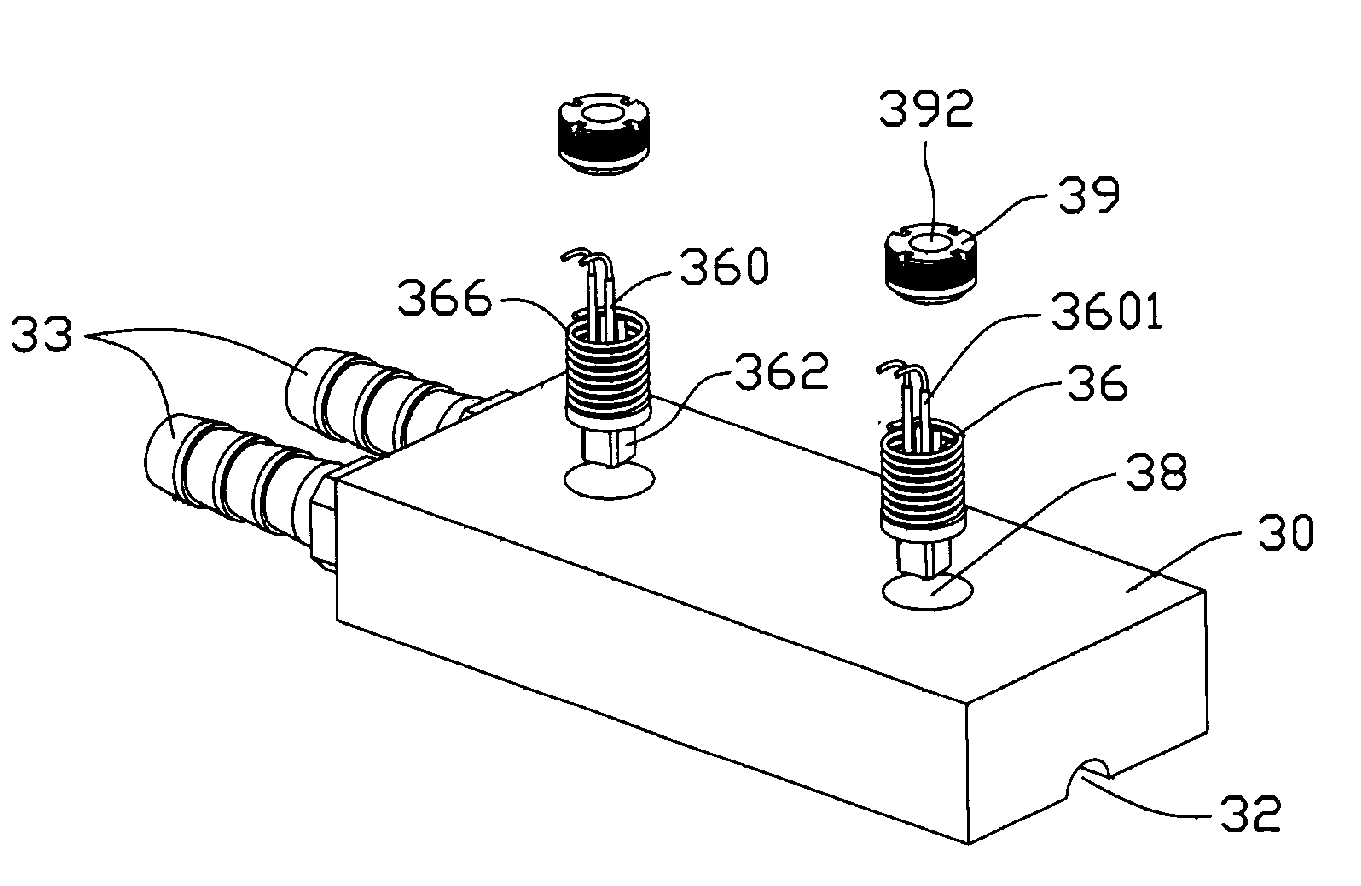
[0032] The two temperature sensors 36 in accordance with FIGS. 3A and 3B work independently and are substantially vertically mounted in two different places on the movable portion 30. Each of the sensors 36 has two wires 360 inserted in two pairs of through apertures 37 vertically extending through the movable portion 30, wherein working (detecting) sections 3602 of the two wires 360 are located in the groove 32. Each of the two wires 360 has two vertical sections 3601 extending into a corresponding pair of apertures 37 of the movable portion 30. The working section 3602 interconnects bottom ends of two corresponding vertical sections 3601. One of the vertical sections 3601 of each wire 360 has an upper extension extending through a corresponding aperture 342 in the board 34 to connect with the monitoring computer.

[0033] In use, the condensing section of the heat pipe is received in the channel 50 when the movable portion 30 moves away from the immovable portion 20. Then the movable...

third embodiment

[0038] the temperature sensor 36 is positioned on the hole 38 of the movable portion 30 via the screw 39 engaging in the hole 38. Therefore, 1) it is easy to install / remove the temperature sensor 36 to / from the movable portion 30; and, 2) it is easy to adjust the compression force of the spring coils to thereby provide suitable force on the working sections 3602 of the wires 360, whereby the working sections 3602 can have an optimal contact with the condensing section of heat pipe. In this embodiment, the bolt 42 is directly secured to the movable portion 30.

[0039] In all the embodiments of the present invention, the wires 360 are perpendicular to the groove 32; and, they can be oriented with other angles in respective to the groove 32, so long as the wires 360 have an intimate contact with the condensing section of the heat pipe when the movable portion 30 moves toward the immovable portion 20.

[0040] The temperature sensors 26 and the immovable portion 20 can have configuration a...


PUM


Abstract

A performance testing apparatus for a heat pipe includes an immovable portion having a cooling structure defined therein for cooling a heat pipe requiring to be tested. A movable portion is capable of moving relative to the immovable portion and has a cooling structure therein for cooling the heat pipe. A receiving structure is located between the immovable portion and the movable portion for receiving the heat pipe therein. At least one temperature sensor is attached to at least one of the immovable portion and the movable portion. The least one temperature sensor has a detecting section exposed in the receiving structure for thermally contacting the heat pipe in the receiving structure to detect a temperature of the heat pipe.

Description

FIELD OF THE INVENTION [0001] The present invention relates generally to testing apparatuses, and more particularly to a performance testing apparatus for heat pipes. DESCRIPTION OF RELATED ART [0002] It is well known that a heat pipe is generally a vacuum-sealed pipe. A porous wick structure is provided on an inner face of the pipe, and phase changeable working media employed to carry heat is included in the pipe. Generally, according to where the heat is input or output, a heat pipe has three sections, an evaporating section, a condensing section and an adiabatic section between the evaporating section and the condensing section. [0003] In use, the heat pipe transfers heat from one place to another place mainly by exchanging heat through phase change of the working media. Generally, the working media is a liquid such as alcohol or water and so on. When the working media in the evaporating section of the heat pipe is heated up, it evaporates, and a pressure difference is thus produ...

Claims


Application Information

Patent Timeline
IPC IPC(8): G01K13/00
CPCF28D15/02F28F2200/005
Inventor LIU, TAY-JIANTUNG, CHAO-NIENSUN, CHIH-HSIENHOU, CHUEN-SHULIN, CHENG-HUI
Owner HON HAI PRECISION IND CO LTD
Learn More