Fluid measurement/division device and process

a technology of fluid measurement and division device, which is applied in the direction of liquid/fluent solid measurement, engine lubrication, and contracting/expanding measuring chamber. it can solve the problems of large and heavy description devices of traditional type, and the cost of traditional devices to constru

Inactive Publication Date: 2007-05-31
SUNBIRD INVESTMENTS
View PDF4 Cites 4 Cited by
  • Summary
  • Abstract
  • Description
  • Claims
  • Application Information

AI Technical Summary

Benefits of technology

[0012] Within the scope of this technical aim, an object of the invention is to provide a device of small size and reduced weight; this advantageously enables devices to be constructed which can be handled and installed easily, even in difficultly accessible or narrow positions.
[0013] Another object of the invention is to provide a device and process which are economical to implement, in particular compared with traditional devices.

Problems solved by technology

However, the described devices of traditional type are large and heavy because of the minimum number of cylinder / piston pairs required for their operation; in this respect, at least three cylinder / piston pairs are required, each of which effects one of the described stages during operation, while the other cylinder / piston pairs effect the others.
The traditional devices are also costly to construct because of the large number of components required.

Method used


Image

  • Fluid measurement/division device and process
  • Fluid measurement/division device and process
  • Fluid measurement/division device and process

Examples


Embodiment Construction

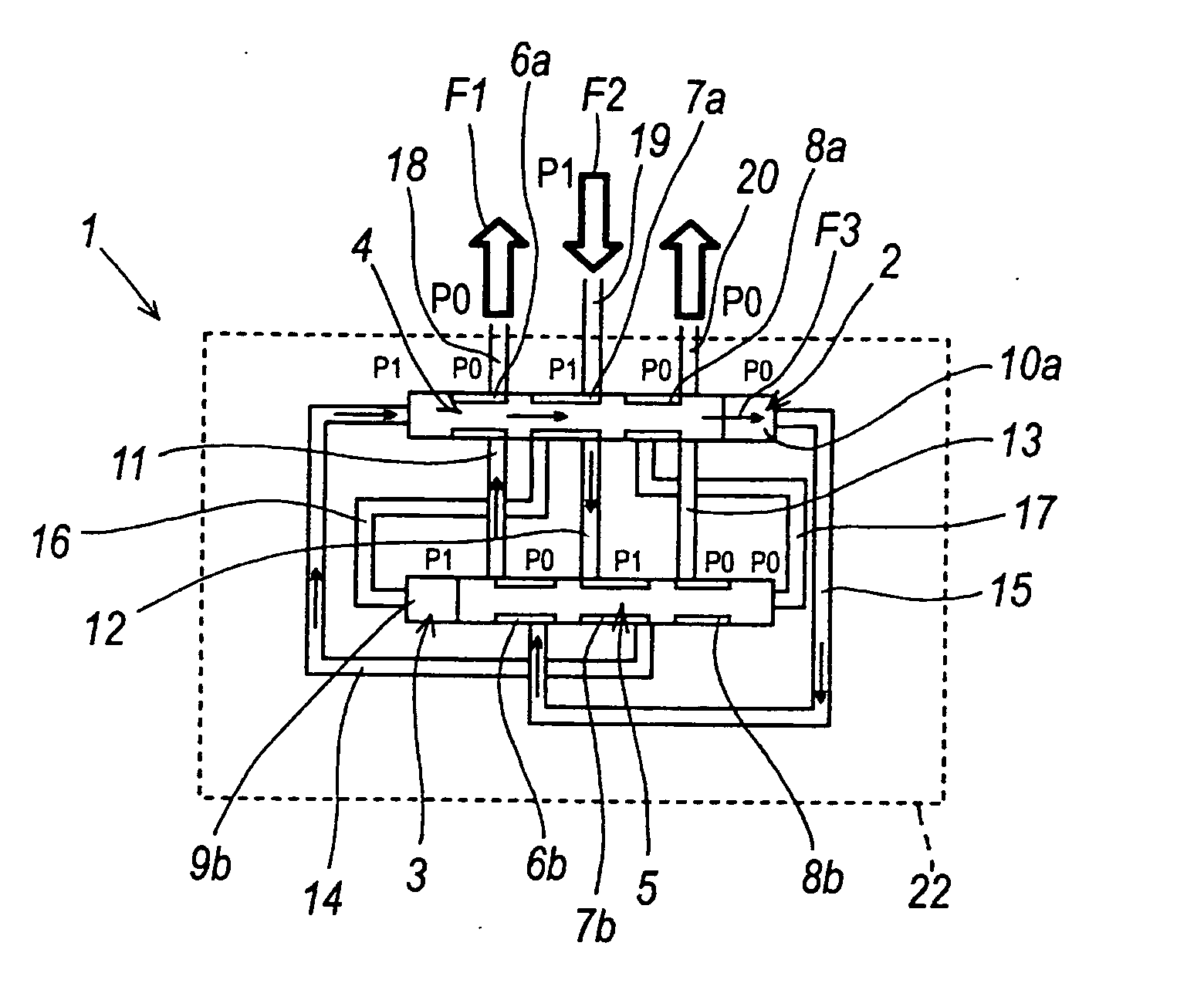
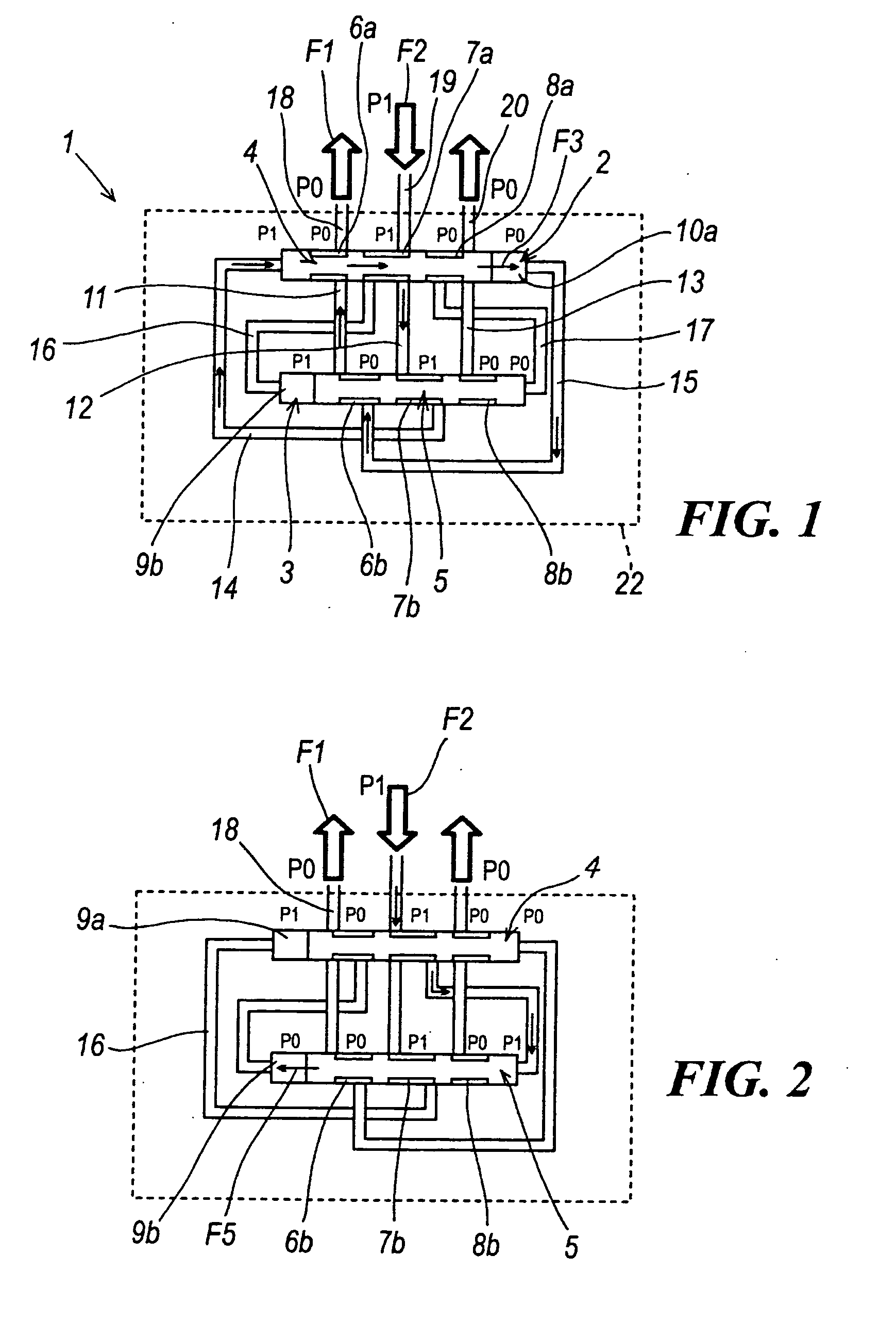
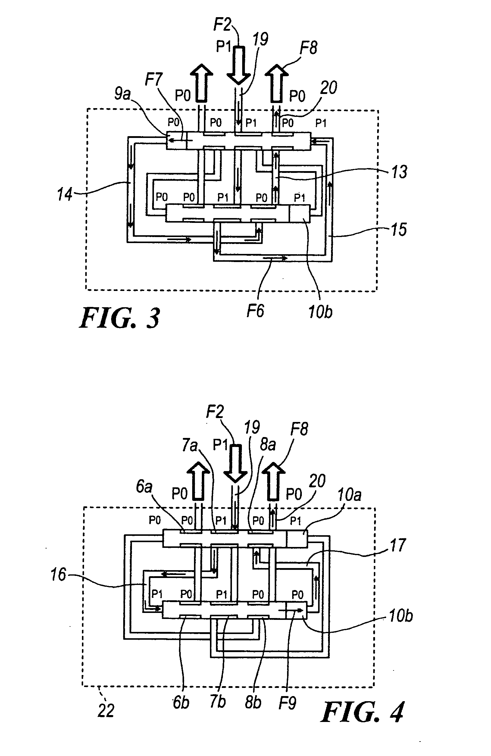
[0024] With reference to said figures, these show a fluid measurement / division device indicated overall by the reference numeral 1.

[0025] The device 1 comprises two cylinders 2, 3 in which a first and a second piston 4, 5 are slidably inserted.

[0026] Each of the two pistons 4, 5 operates alternately as a fluid dosing piston or as a piloting piston for the dosing piston.

[0027] The dosing piston dispenses fluid to the outside (by its movement), while the piloting piston defines the path for the fluid, which is directed towards the dosing piston to control its movement.

[0028] Advantageously, the first and second piston 4, 5 present reduced diameter regions which, together with the surface of the cylinders 2, 3, define three constant volume distribution chambers 6a, 7a, 8a and two variable volume pumping chambers 9a, 10a for the first cylinder 2, and three constant volume distribution chambers 6b, 7b, 8b and two variable volume pumping chambers 9b, 10b for the second cylinder 3.

[00...


PUM


Abstract

The fluid measurement / division device comprises a plurality of cylinders in which a first and a second piston are slidably inserted to operate alternately as a dosing piston or as a piloting piston for the dosing piston. The first and said second piston present reduced diameter regions which, together with the surface of the cylinders, define at least three constant volume distribution chambers and two variable volume pumping chambers. The device comprises a plurality of conduits connecting said cylinders together and to the outside, to allow or prohibit hydraulic connection in relation to the position assumed by the first and by the second piston, such that when the first piston is in the dosing stage and, by translating, it dispenses fluid and passes to the piloting stage, the second piston passes from the piloting stage to the dosing stage via a neutral stage.

Description

FIELD OF THE INVENTION [0001] The present invention relates to a fluid measurement / division device and process. BACKGROUND OF THE INVENTION [0002] In particular, the device and process of the present invention are usable to divide a fluid flow rate, for example to obtain from an inlet flow two or more outlet flows of equal flow rate, with possible measurement of the flow rate. If only one flow is obtained at the device outlet, the device is used (and operates) as a flow rate measurement device, i.e. it exactly measures the delivered flow rate without effecting any flow rate division. DISCUSSION OF THE RELATED ART [0003] Devices of the indicated type are currently formed with at least three cylinders, in each of which a piston is slidably inserted. [0004] Each piston is provided with two reduced diameter regions which define two distribution chambers inside the cylinder. Each cylinder also defines two pumping chambers at its ends. [0005] The three cylinders are connected together by ...

Claims


Application Information

Patent Timeline
Patent Type & Authority Applications(United States)
IPC IPC(8): F04B17/00
CPCF16N25/02F16N27/00G01F3/18G01F11/04
Inventor DIVISI, WALTER
Owner SUNBIRD INVESTMENTS
Why Eureka
Try Eureka