Medication injector apparatus with drive assembly that facilitates reset

a technology of drive assembly and injector, which is applied in the direction of instruments, infusion syringes, surgery, etc., can solve the problems of increasing the overall girth inconvenient initial priming insufficient design, etc., to facilitate the reset of the injection pen, reduce the effect of flywheel effect, and small drive clutch

Inactive Publication Date: 2007-05-31
ELI LILLY & CO
View PDF26 Cites 266 Cited by
  • Summary
  • Abstract
  • Description
  • Claims
  • Application Information

AI Technical Summary

Benefits of technology

[0024] One advantage of the present invention is that a drive assembly can be provided which facilitates reset of an injection pen during installation of a replacement medication cartridge.
[0025] Another advantage of the present invention is that a drive assembly can be provided which, without increasing the injection force of the injection pen in which it is used, allows for a biasing element strong enough to force the drive clutch out of engagement with the drive member, thereby avoiding a problem found in the prior art in which a more weakly biased drive clutch could bind to the drive member so as to lock the drive screw and prevent reset.
[0026] Another advantage of the present invention is that a drive assembly can be provided which has a relatively small drive clutch to limit flywheel effects during drive screw reset, which in turn may reduce priming volumes.
[0027] Another advantage of the present invention is that a drive assembly can be provided which engages a cartridge assembly during its mounting to the pen base so as to reduce play between the cartridge assembly and the pen base, thereby providing an improved fit therebetween and improved quality feel to the injection pen.
[0028] Another advantage of the present invention is that a drive assembly with a relatively simple design can be provided to reduce costs of assembly and manufacture.
[0029] Another advantage of the present invention is that a drive assembly can be provided which in one embodiment spring biases forward a loaded cartridge to hold it in place against a forward stop of the holder or retainer of the cartridge assembly to ensure a stable platform for dose delivery.

Problems solved by technology

For example, due to the relatively large size of the drive clutch, a flywheel effect of the rotating clutch during screw resetting may cause the screw to retract so far that the initial priming of the pen may be inconvenient to perform.
While useful, this injection clicker design is not without its shortcomings.
Still further, the radially extending leaf springs may undesirably increase the overall girth of the injection pen.
For example, because the spring used within the injection audible feedback design is also used as part of the dialing audible feedback design, the injection audible feedback cannot be tuned or adjusted by modifying that spring without also affecting the dialing audible feedback, and potentially other features such as dialing torque.
Another limitation of reusable injection pens is that because different types of medicines, provided in separate cartridges, possibly may be utilized with the same reusable pen body, a user of the injection pen and those various cartridges needs to be vigilant to ensure the pen is used to administer the correct dosage of medicine.
While useful, the information provided does not necessarily result in the delivery device indicating to a user the actual dose of medicine being administered by the delivery device, and calculation errors on the part of the user are possible, resulting in incorrect doses.
Another limitation of some injection pens relates to the dose setting mechanism.
However, the use of cams to activate the switches results in the resistance to rotating the operating head noticeably varying during revolution of that operating head.
Another problem with some existing injection pens is that dosing and injecting operations of the pen are not intuitive to all users.
However, such a belief is erroneous for at least one pen design, and therefore a user who operates under such an erroneous belief may not properly self-administer the desired medicine.
However, while useful, this design is not without its shortcomings.
For one thing, during plunging, few if any of the dose-indicating numbers which have been passed in setting the pen are displayed, which may be a source of confusion for some users.

Method used


Image

  • Medication injector apparatus with drive assembly that facilitates reset
  • Medication injector apparatus with drive assembly that facilitates reset
  • Medication injector apparatus with drive assembly that facilitates reset

Examples


Embodiment Construction

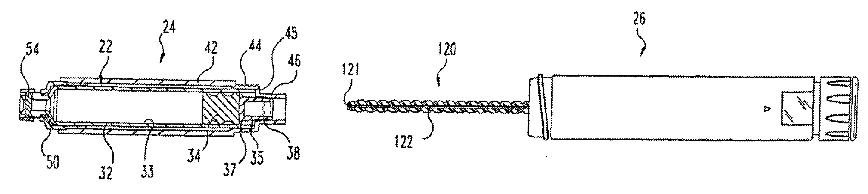
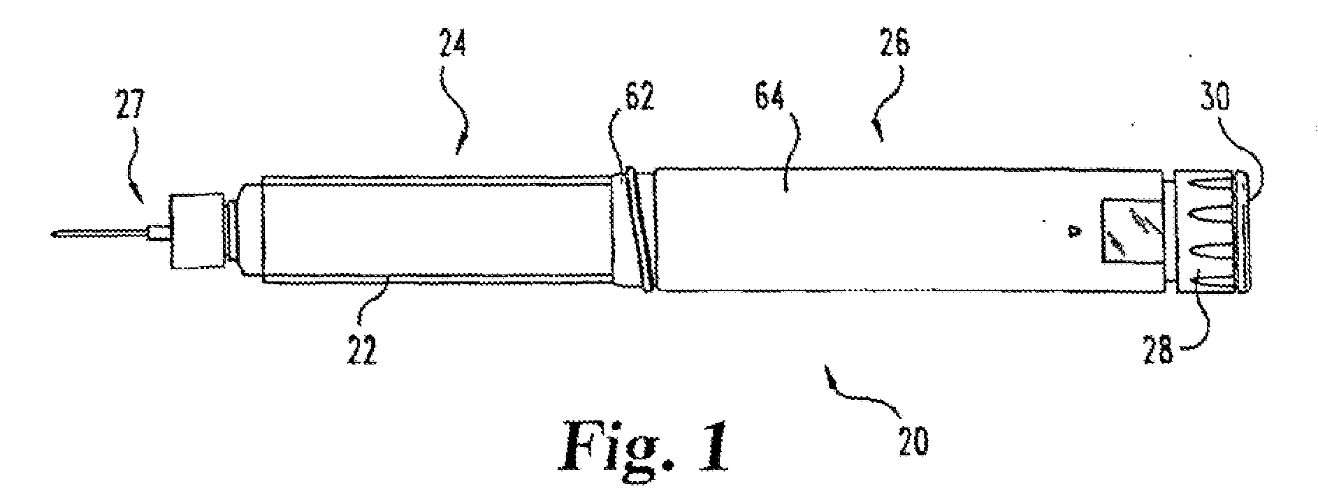
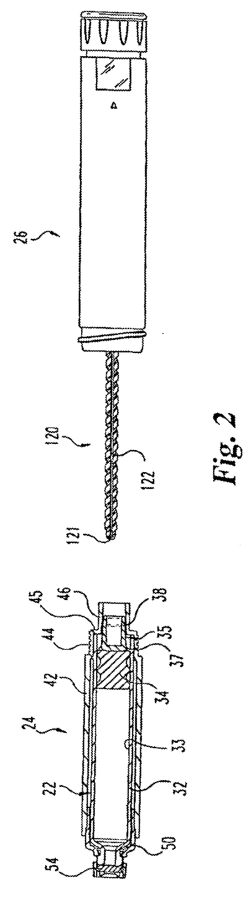
[0079]FIG. 1 generally illustrates one type of medication delivery device in which a drive assembly of the present invention finds beneficial application. The shown delivery device is a reusable, medication injection pen, generally designated 20. As is generally known in reusable devices of its type, injection pen 20 includes a medication filled cartridge 22 as part of a cartridge assembly, generally designated 24, which is connected to a reusable pen base, generally designated 26. Pen base 26 preferably includes dose setting and injecting mechanisms that function to allow a quantity of medicine to be selected and then expelled from cartridge assembly 24 through the injection needle assembly 27 shown attached thereto. In the shown embodiment, an exposed knob 28 with rotatable button 30 thereon at the rearward or proximal end of pen base 26 is a manually operable portion of the dose setting and injecting mechanisms otherwise housed within pen base 26. During the dose setting process,...


PUM


Abstract

A medication injector apparatus such as an injection pen. The injection pen includes a resettable, cartridge plunger drive assembly including an axially floating nut, a cartridge plunger engaging screw, and a drive clutch movable with the nut and which when rotated causes the screw to screw through the nut. When a cartridge assembly is mounted to the pen base, the floating nut and drive clutch are shifted proximally such that the drive clutch is in torque transmitting engagement with a rotatable drive member of the pen, such that rotation of that drive member results in drive screw advancement through the nut in the distal direction. When the cartridge assembly is not mounted to the pen base, the floating nut and drive clutch are biased distally to disengage the drive clutch from torque transmitting engagement with the rotatable drive member and to thereby allow the drive screw to be reset proximally through the nut to a position more retracted within the pen base. The injection pen also may include an injection clicker assembly having a collar arranged coaxially on a drive sleeve and which oscillates axially on the drive sleeve that rotates during medication dispensing to provide an audible clicking sound that indicates injecting use of the pen. The injection pen also may include a doseable quantity identifier that uses a rotational matrix and a sensor for electrically sensing the arrangement of the dose setting mechanism of the pen, which identifier may be part of a therapeutic dose indicating system that utilizes a cartridge recognizer to recognize a concentration of medication so as to allow an automatic determination of a therapeutic dose. The injection pen further may include an assembly for selectively rotating a drive sleeve of the pen, which assembly has a dial that rotates out during dose setting and which translates in without rotation during dose injecting.

Description

BACKGROUND OF THE INVENTION [0001] The present invention pertains to medication delivery devices, and, in particular, to portable medication delivery devices such as injection pens. [0002] Patients suffering from a variety of diseases, such as diabetes, frequently must inject themselves with medication, such as insulin solutions. To permit a person to conveniently and accurately self-administer proper doses of medicine, a variety of devices broadly known as injector pens or injection pens have been developed. [0003] In order to permit a person to administer a proper dose, injection pens have been equipped with a wide variety of dosing and injecting mechanisms that enable a particular dosage to be conveniently selected and then dispensed. Generally, these pens are equipped with a cartridge including a plunger and containing a multi-dose quantity of liquid medication. A drive member is movable forward to advance the plunger in the cartridge in such a manner to dispense the contained m...

Claims


Application Information

Patent Timeline
Patent Type & Authority Applications(United States)
IPC IPC(8): A61M5/00A61M5/315A61M5/31A61M5/24G01D5/249G01D5/25
CPCA61B2017/00482A61M5/24A61M5/3129A61M5/31535A61M5/31543A61M5/31551A61M5/31556A61M5/31558A61M5/31568A61M5/31573A61M5/31575A61M5/31585A61M5/31593A61M2005/2407A61M2005/2488A61M2005/3125A61M2205/50A61M2205/581A61M2205/583A61M2205/585A61M2205/60G01D5/2497G01D5/25A61M2205/6027A61M5/31566
Inventor ATTERBURY, WILLIAM GODWINDILLER, MARK GERARDGAYDOS, PETER ANDREWHOSTE, SHANNON MARIE-LYNNTAYLOR, DONNA MARIEWALTER, BOBBY LEEMADLAND, STEVEN MICHAELBOYD, DOUGLAS EDWARD
Owner ELI LILLY & CO
Why Eureka
Try Eureka