Device for forming a drill hole in bone

a drill bit and bone technology, applied in the field of bone drill bit devices, can solve the problems of visible instability in the knee joint, subsequent instability in the patient's knee joint, etc., and achieve the effect of easy manipulation and easy targeting of the femoral attachmen

Inactive Publication Date: 2007-05-31
KARL STORZ GMBH & CO KG
View PDF20 Cites 26 Cited by
  • Summary
  • Abstract
  • Description
  • Claims
  • Application Information

AI Technical Summary

Benefits of technology

[0055] This measure has the advantage that the device can be easily manipulated in the operating surgeon's hand. An angled handgrip can be guided by the operating surgeon such that his hand does not have to be held at an unnatural angle d

Problems solved by technology

Even slight deviations can lead to subsequent instability in the patient's knee joint.
Th

Method used


Image

  • Device for forming a drill hole in bone
  • Device for forming a drill hole in bone
  • Device for forming a drill hole in bone

Examples


Embodiment Construction

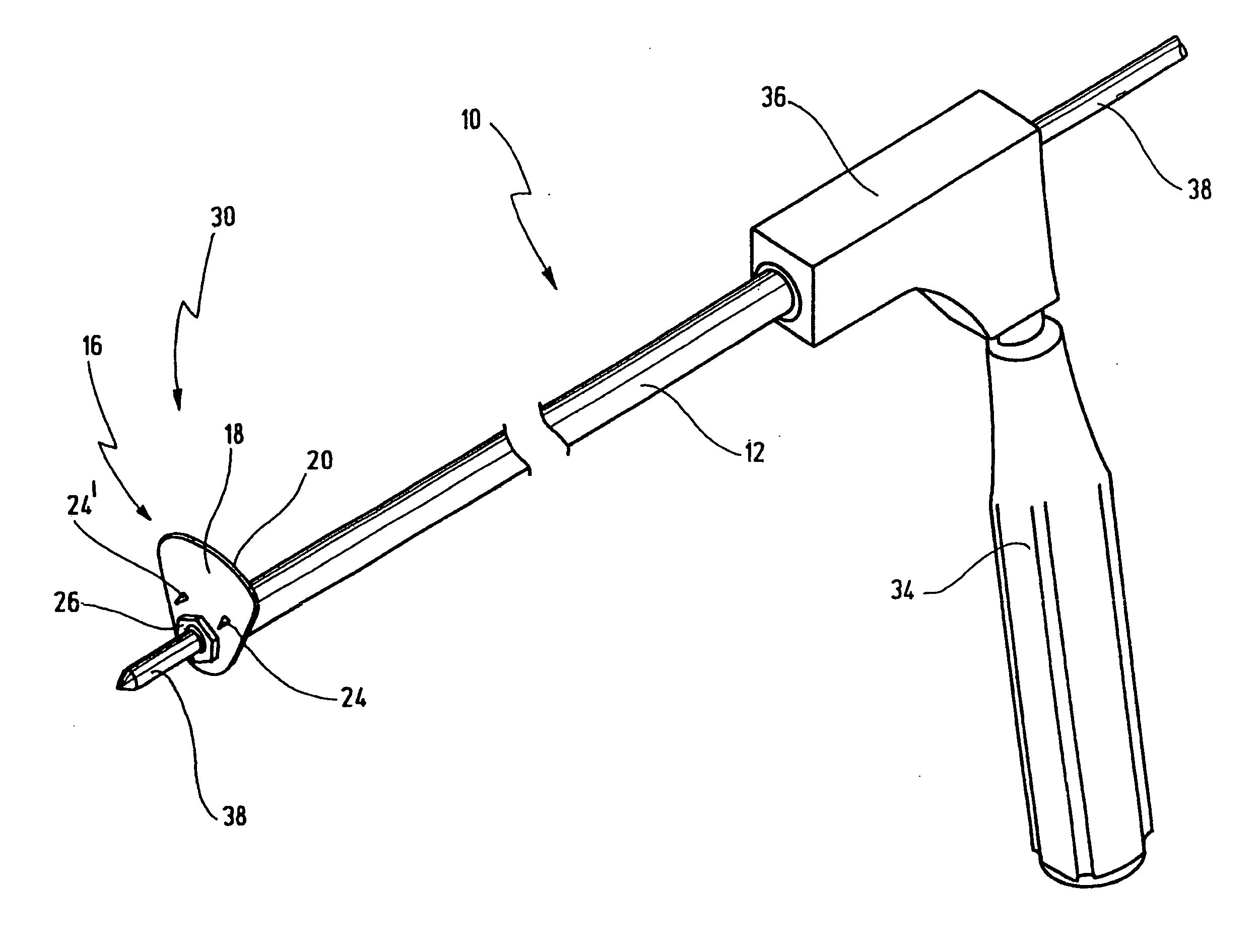
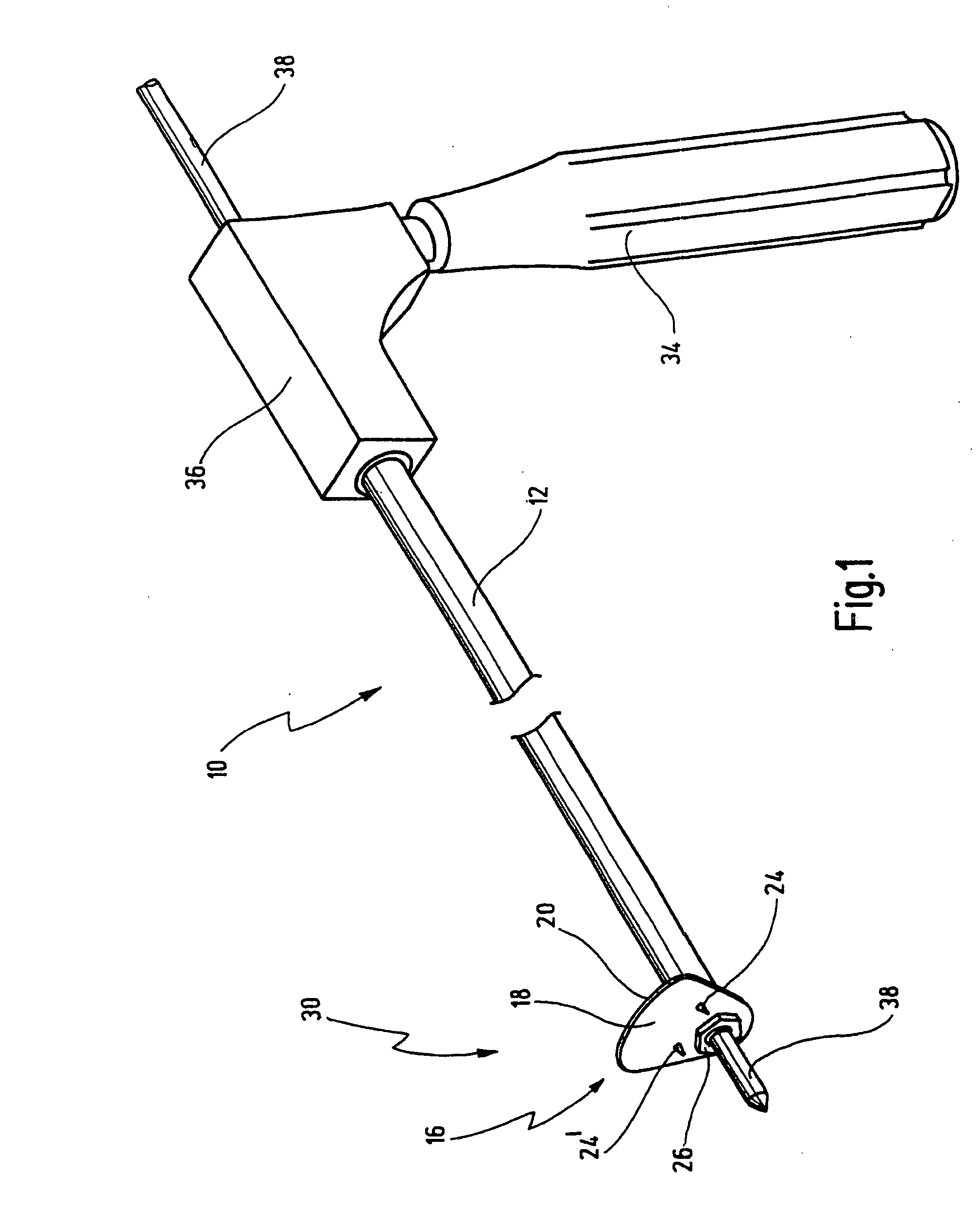
[0067] In FIGS. 1 and 7, a device for correctly targeted formation of a drill hole is designated in its entirety by reference number 10.

[0068] The device 10 according to the invention comprises a hollow shaft 12. The hollow shaft 12 is received at a proximal end area in a housing 36. The hollow shaft 12 is guided through this housing 36. At a proximal outlet end, the hollow shaft 12 finishes flush with the housing 36. A drill wire 38 can be guided through this outlet end, as is shown in FIGS. 1 and 7.

[0069] A handgrip 34 protrudes from the housing 36 approximately at right angles to the longitudinal axis of the hollow shaft 12. This handgrip 34 is designed for gripping by the human hand.

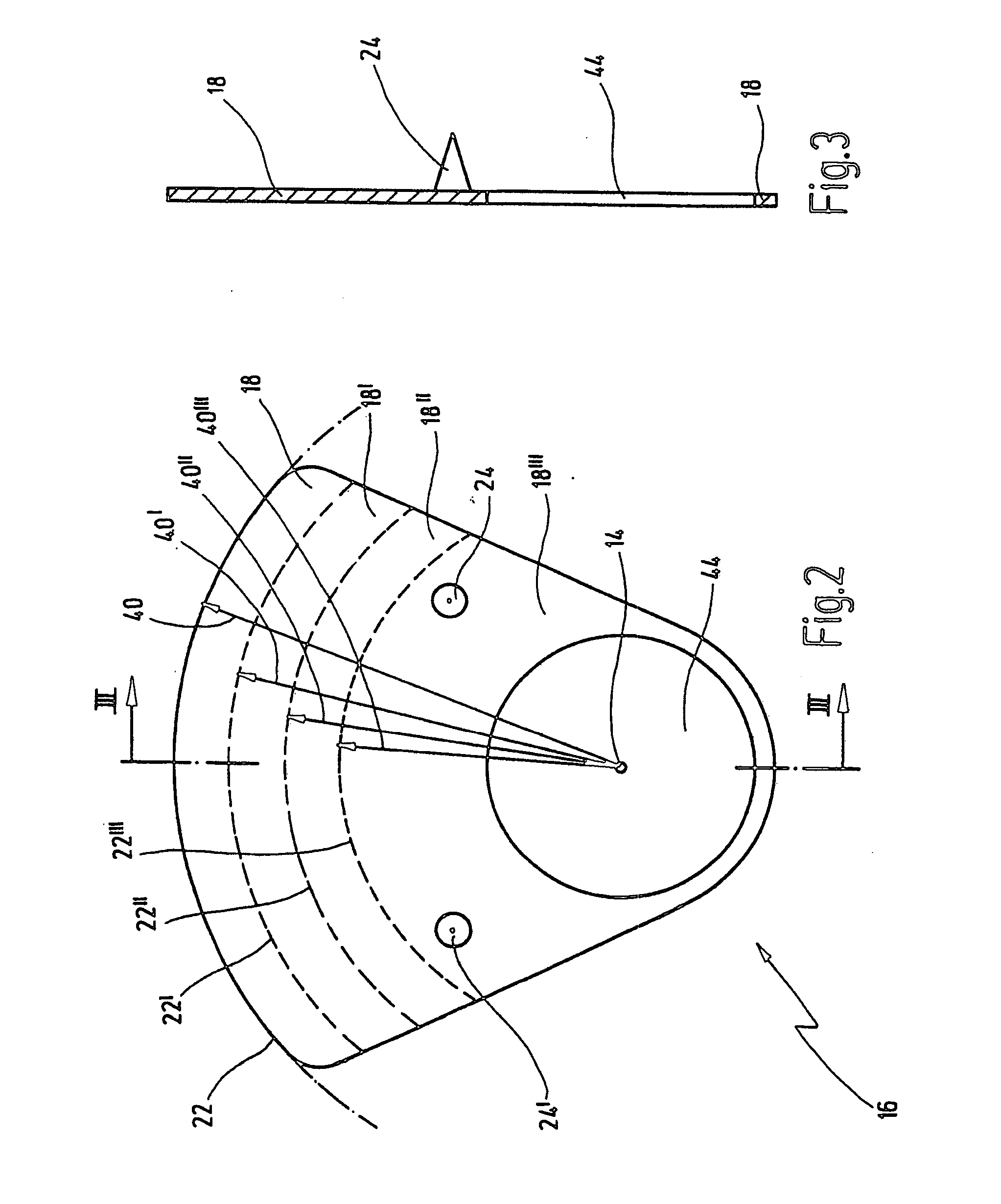
[0070] A sighting element 16 is arranged at a distal end area 30 of the hollow shaft 12. This sighting element 16 extends approximately diametrically to the handgrip 34.

[0071] This sighting element 16 is designed as a disk-like body 18. The body 18 has roughly the shape of a quarter disk. The dis...


PUM


Abstract

A device for a correctly targeted formation of a drill bore centrally in a femoral attachment site of a posterior cruciate ligament of a knee joint comprises a hollow shaft for guiding a drill wire therethrough and a sighting element arranged at a distal end of the hollow shaft. Said sighting element has an edge for placing said sighting element via said edge to an outer margin of a femoral attachment site of a posterior cruciate ligament.

Description

CROSS-REFERENCE TO RELATED APPLICATIONS [0001] The present application claims priority of German patent application No. 10 2005 019 727.2 filed on Apr. 22, 2005, the content of which is incorporated herein by reference. BACKGROUND OF THE INVENTION [0002] The invention relates to a device for a correctly targeted formation of a drill hole centrally in the femoral attachment site of the posterior cruciate ligament of a knee joint, said device comprising a hollow shaft through which a drill wire can be guided. [0003] Devices of this kind, called femoral sighting devices, for introducing a drill wire into a femur are marketed by the Applicant. [0004] A femoral sighting device is illustrated in the book entitled “Arthroskopische Chirurgie” [Arthroscopic Surgery] by Doctor Michael Strobel, Arthroskopische Chirurgie, Springer Verlag Berlin Heidelberg 1998, chapter 2, page 513, FIGS. 2.15-8.a. [0005] This device is more or less in the shape of a screw driver. The device comprises a hollow s...

Claims


Application Information

Patent Timeline
IPC IPC(8): A61B17/60
CPCA61B17/1714A61B17/1764A61B17/8897
Inventor BERBERICH, SASCHAWEILER, ANDREAS
Owner KARL STORZ GMBH & CO KG
Why Eureka
Try Eureka