
Gas turbine engine auxiliary component mount

a gas turbine engine and auxiliary component technology, applied in the direction of machine/engine, machine supports, curtain suspension devices, etc., can solve the problems of fan-blade out event, high shock load, and conventional mounting systems may become subject to a high degree of shock load, and achieve low weight, effective effect, and low production cos

Active Publication Date: 2007-06-07
HAMILTON SUNDSTRAND CORP
View PDF41 Cites 23 Cited by
  • Summary
  • Abstract
  • Description
  • Claims
  • Application Information

AI Technical Summary

Benefits of technology

[0010] The energy absorbing mount system of the present invention provides a mount system for a gas turbine engine auxiliary component that is light in weight, relatively inexpensive to produce, and yet effectively and reliably absorbs a shock load from a fan-blade out event.

Problems solved by technology

Conventional mounting systems may become subjected to a high degree of shock loading not experienced during normal engine operating conditions.
For example, a high shock load may result from a fan-blade out event.
A fan-blade out event results in an imbalance in the engine rotor body which may also cause outward deflection and a rotor body shaft imbalance.
Although effective, conventional mount systems are manufactured with relatively heavy and bulky hardware to provide the high strength and durability to resist normal engine operating conditions as well as the high shock loads to prevent separation of the auxiliary components from the engine casing.

Method used


Image

  • Gas turbine engine auxiliary component mount
  • Gas turbine engine auxiliary component mount
  • Gas turbine engine auxiliary component mount

Examples


Embodiment Construction

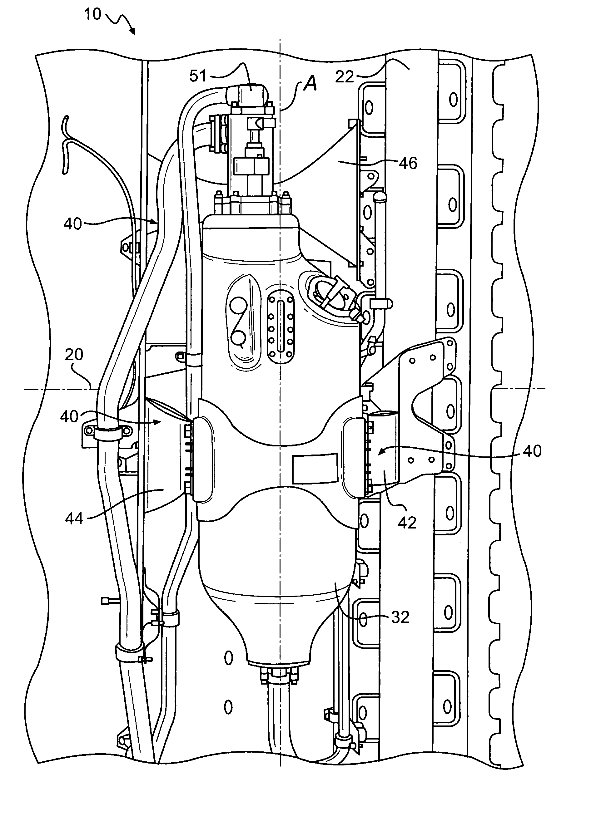
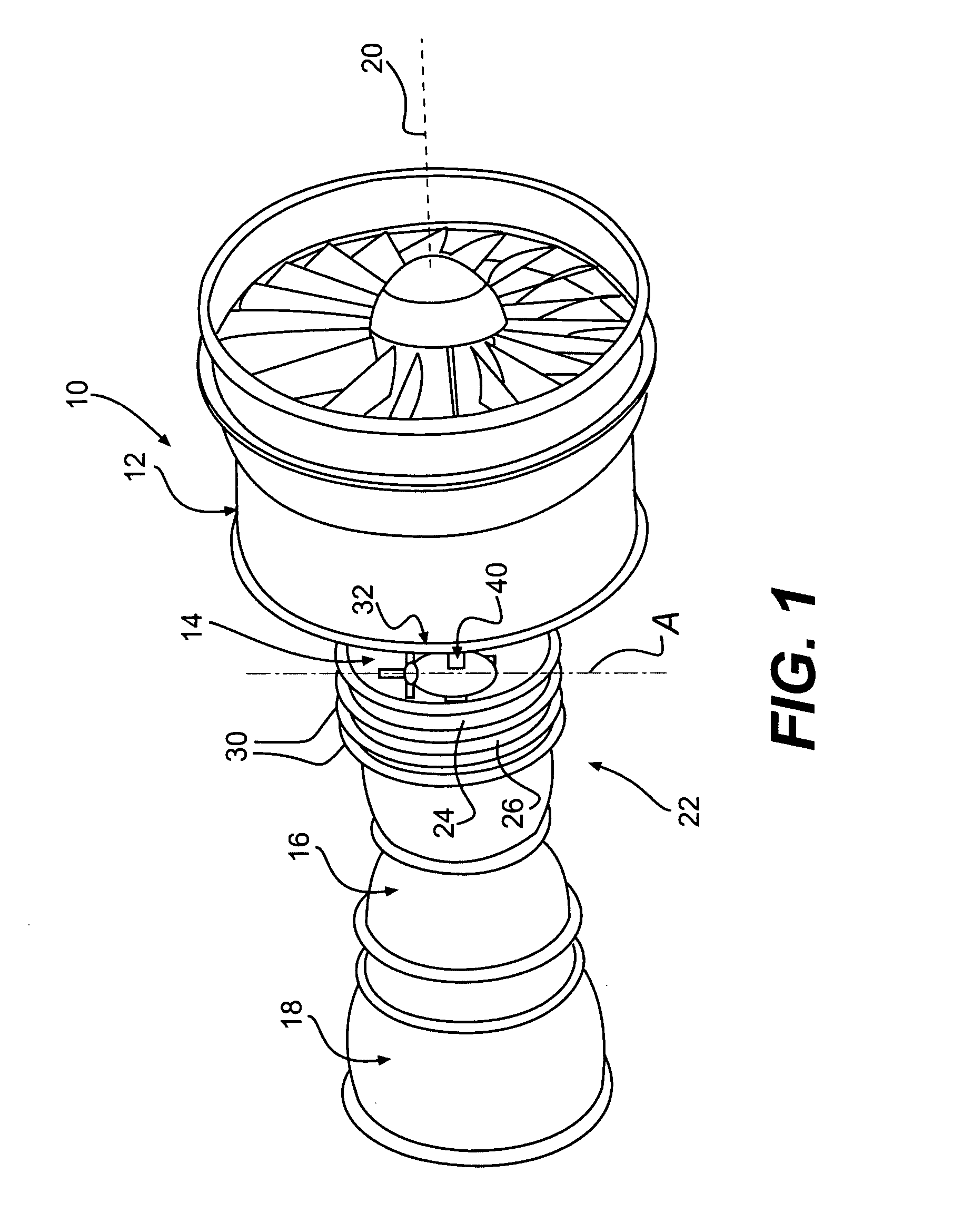
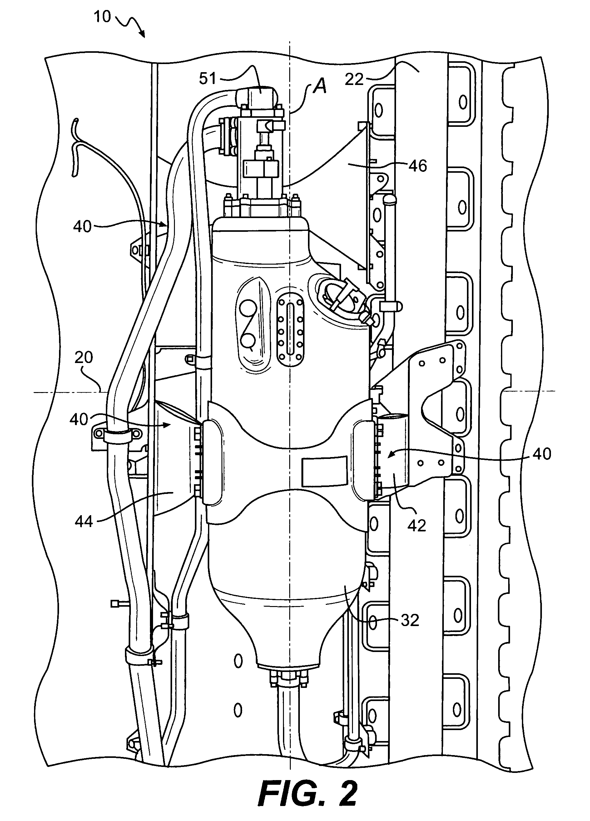
[0019] Referring to FIG. 1, a gas turbine engine 10 generally includes a fan section 12, a compression section 14, a combustion section 16 and a turbine section 18. The compression and turbine sections each contain one or more stages of a compressor and a turbine (not shown) which rotate about an engine longitudinal axis 20. The components of the gas turbine engine 10 are circumscribed by an essentially cylindrical engine casing 22. The engine casing 22 serves as a main structural support for the gas turbine engine 10. The engine casing 22 is usually constructed of individual case sections, such as case sections 24 and 26, which are joined together at bolted flanges such as engine case flange 30.

[0020] An auxiliary component 32 is mounted to the engine casing 22 by a mount system 40 along an auxiliary component axis A which is generally transverse to the engine longitudinal axis 20. The auxiliary component 32 may include any component known in the art that requires mounting to the ...


PUM

PropertyMeasurementUnit
Gravityaaaaaaaaaa
Strengthaaaaaaaaaa
Tensile strengthaaaaaaaaaa

Abstract

A mount system for an auxiliary component includes two side brackets and a top bracket for rigidly attaching an auxiliary component to an engine casing. Each side bracket defines mount segments, a deformable member and two retainer members between the mount segment. The deformable member plastically deforms during a fan-blade out event, thereby absorbing a majority of the high shock load experienced on the auxiliary component. The retainer members maintain the attachment between the auxiliary component and the engine casing subsequent to the fan-blade out event.

Description

BACKGROUND OF THE INVENTION [0001] The present invention relates to a mounting system, and more particularly to an energy absorbing mount system for a gas turbine engine auxiliary component. [0002] Gas turbine aircraft engines utilize a turbine fan to draw ambient air into the engine for compression and combustion by the engine. The turbine fan is shrouded by an engine casing. Typically, a variety of auxiliary components such as engine oil tanks, gearboxes, valves, control systems for regulating the engine's operations, and other components are mounted to the engine casing. Various mounting systems mount the auxiliary components to the engine casing. [0003] Conventional mounting systems typically include a plurality of rigid bracket members that are attached between the auxiliary component and the engine casing by a series of shear pins. Such conventional mounting systems may also include isolators that damp the transmission of engine vibratory loads to the auxiliary components duri...

Claims


Application Information

Patent Timeline
IPC IPC(8): F02C7/32
CPCF01D21/045F02C7/32Y02T50/671F05D2220/50Y10T29/53961F05D2300/501Y10S248/909Y10T29/49826F05D2240/90Y02T50/60B64D41/00
Inventor CALLAGHAN, CRAIG M.
Owner HAMILTON SUNDSTRAND CORP
Learn More