Condensing gas fired water heater

a gas fired water heater and condensing technology, applied in water heaters, fluid heaters, lighting and heating equipment, etc., can solve the problems of low combustion efficiency, difficult access to tubes and support plates, and loss of heat, so as to facilitate heat transfer, facilitate leakage, and facilitate the effect of reducing the number of cylinders

Inactive Publication Date: 2007-06-07
PVI IND +1
View PDF7 Cites 11 Cited by
  • Summary
  • Abstract
  • Description
  • Claims
  • Application Information

AI Technical Summary

Benefits of technology

[0012] The preferred combustion chamber comprises a substantially cylindrical body portion having an open end located adjacent the closed tank bottom opening and an opposite closed end. The multiple external heating surfaces preferably comprise a plurality curved fire tubes, the fires tubes each having a short leg joined to the closed end of the combustion chamber and a long leg which curves downwardly and exits the closed tank adjacent the bottom opening thereof. A flue collector is mounted on the exterior of the closed tank adjacent the bottom opening thereof, the flue collector having an annular chamber surrounding the exterior mounted blower and separated therefrom. The annular chamber communicates with each long leg of each of the fire tubes for collecting flue gases and condensate formed therein. The flue collector is preferably formed as a seamless lower portion with upturned walls so as to facilitate a leak free area without seams where an acidic condensate might collect.
[0013] Preferably, the water inlet of the closed tank is located on the tank sidewalls at a point proximate the exit point of the long legs of the curved fire tubes from the closed tank into the flue collector to facilitate heat transfer. At least selected ones of the curved fire tubes are provided with baffles to increase flue velocity and increase impingement of flue gases on an inner wall surface of the fire tubes. The fire tube interiors are divided into a condensing region and a non-condensing region and non-metallic plastic baffles may be located in the condensing region of the fire tube interiors. In a particularly preferred embodiment of the invention, the baffles are corkscrew in shape and may have cylindrical plastic rods placed in a condensing region of the fire tube interiors.
[0014] The preferred normally closed water storage tank is provided with a bottom mounting flange. A circular, flat metal sheet is used as a lower closure for the normally closed tank as well as for mounting the forced draft burner assembly, the flat metal sheet being gasketed and bolted to the bottom mounting flange of the tank. The burner may be equipped with a variable orifice arrangement for controlling the intake of combustion air to the combustion chamber. An electrical control panel is mounted on the rotomolded jacket by means of a floating mounting stud on the closed tank exterior cylindrical sidewalls in cooperation with a positive attachment to a flange surface molded into the rotomolded plastic jacket. The control panel can be equipped with a special hinged door arrangement which provides a positive attachment mechanism for mounting the door on the panel.

Problems solved by technology

The location of the combustion chamber on the exterior of the water heater resulted in lost heat and lower combustion efficiency.
The tubes and support plates were not easily accessible and required disassembly of the entire tank for maintenance and replacement.
However, the combustion chamber and burner assembly were typically horizontally mounted and the design was not a “condensing” design.

Method used


Image

  • Condensing gas fired water heater
  • Condensing gas fired water heater
  • Condensing gas fired water heater

Examples


Embodiment Construction

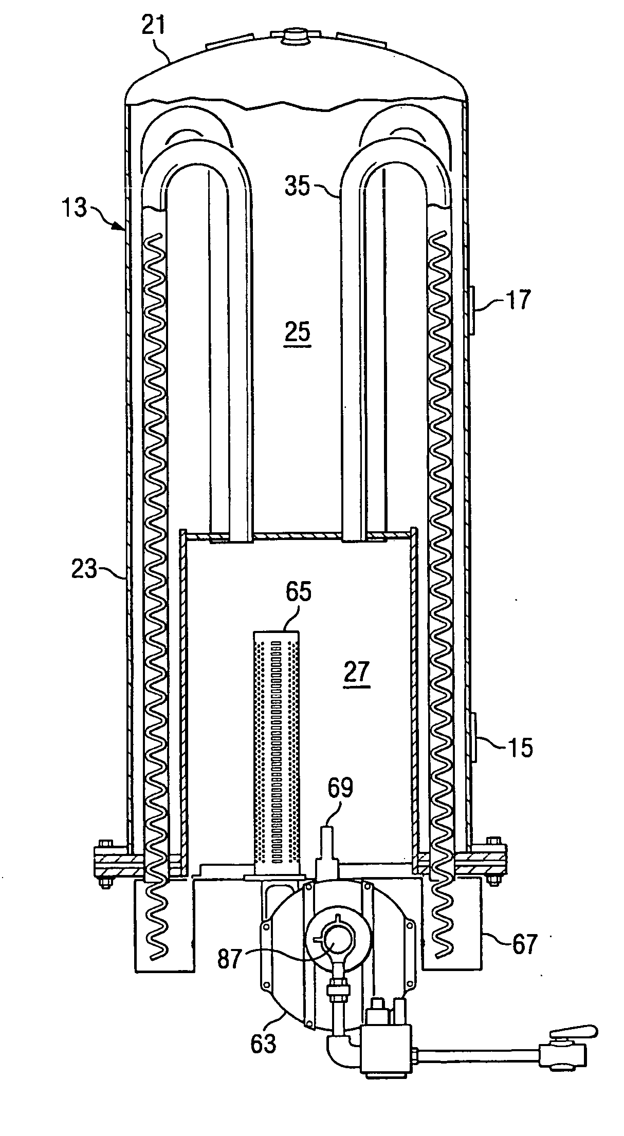
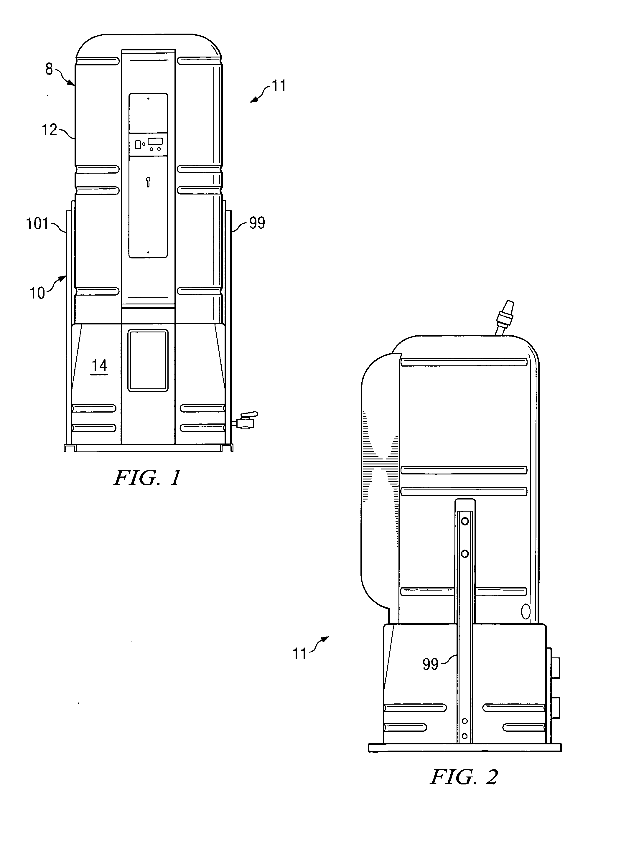
[0033]FIG. 1 shows the water heater of the present invention designated generally as 11. The term “water heater”, as used in this discussion, will be understood to encompass a heating boiler, depending upon the sizing and capacities of the various components to be described.

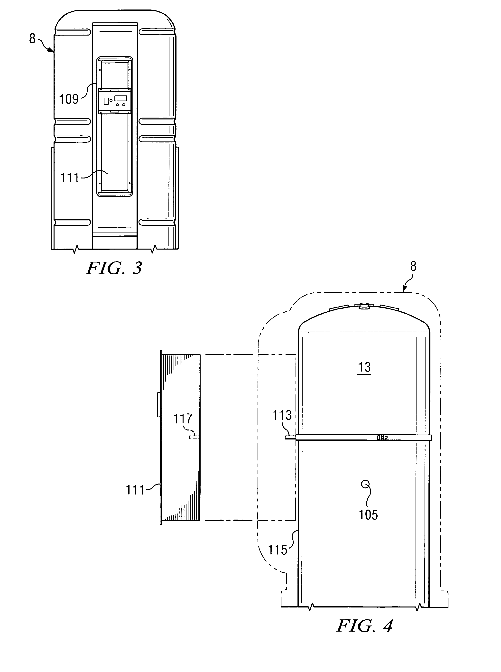
[0034] The water heater 11 includes a rotomolded outer jacket 8 formed from a synthetic, non-conductive material and a support stand 10 for supporting the water heater in a normal vertical operating position. In the embodiment of the invention shown in FIGS. 1 and 2, the jacket is provided as a one-piece upper section 12 and a two-piece “clam shell” lower enclosure 14. It will be understood, however, that the rotomolded outer jacket could also be comprised of several large connectible vertical segments that can be connected together to form various diameter outer enclosures. Alternatively, the rotomolded jacket design could also be comprised of two or more interlocking rotomolded rings which can be connected tog...


PUM


Abstract

A water heater is shown having a closed metal tank with an upwardly mounted combustion chamber and burner/blower assembly. Curved fire tubes convey the products of combustion from the chamber to an exterior mounted flue assembly. The closed tank is enclosed by a rotomolded jacket. A support stand with vertically arranged support legs supports the tank in a normally vertical position but also allows the tank to be pivoted to a horizontal position on the support stand for maintenance or repair operations.

Description

CROSS REFERENCE TO RELATED APPLICATION [0001] The present application claims priority from provisional application Ser. No. 60 / 738,815, filed Nov. 22, 2005, entitled “Condensing Gas Fired Water Heater,” by the same inventors.BACKGROUND OF THE INVENTION [0002] 1. Field of the Invention [0003] The present invention relates generally to a fire tube water heater / heating boiler having a pressurized, submerged combustion chamber and curved, submerged fire tubes, the flue products produced within the fire tubes being cooled below their dew point, causing water vapor normally entrained in combustion gases to condense to a liquid on the heating surfaces of the fire tubes. [0004] 2. Description of the Prior Art [0005] In conventional gas / oil fired water heaters, hot gas flows through a series of vertically mounted tubes which are mounted in vertical fashion between top and bottom support plates within the water heater tank. Water flows into and out of a chamber located between the support pla...

Claims


Application Information

Patent Timeline
Patent Type & Authority Applications(United States)
IPC IPC(8): F24H1/00
CPCF24H1/206F24H9/1836
Inventor HUBBARD, MICHAEL JAMESFERGUSON, MARK ALLENMYERS, FRANK AUSTINBOTHNER, PAUL JAMES
Owner PVI IND
Why Eureka
Try Eureka