Self-heating container

a self-heating container and container technology, applied in the field of containers, can solve the problems of affecting the quality of the seal, requiring many parts to be sealed, and complex assembly, and achieve the effect of cost-effective manufacturing and simple design

Inactive Publication Date: 2007-06-07
HEAT WAVE TECH
View PDF24 Cites 48 Cited by
  • Summary
  • Abstract
  • Description
  • Claims
  • Application Information

AI Technical Summary

Benefits of technology

[0017] The containers of the preferred embodiments of the present invention are simple in design and cost efficient to manufacture.

Problems solved by technology

A disadvantage of this container is that in assembly, placing and securing the membrane, which is a critical step, can be complicated, and sophisticated testing steps would be required to ensure that the seal is secure, Filling the lower compartment with water must be done with precision as any water present in the vicinity of the seal can adversely effect the quality of the seal.
A disadvantage of this container is that assembly is quite complicated.
A disadvantage of this container is that it requires many of the parts to be sealed.
Seals can be easily broken when the container undergoes a temperature change, jeopardizing the integrity of the container.
The container of the '879 patent has a complex design and too many parts.
Although various self-heating technology and self-heating container designs have been around for a while, self-heating containers have not be widely commercialized in the marketplace.
This is because none of the existing designs are sufficiently simple to enable manufacturing at a reasonable cost.

Method used


Image

  • Self-heating container
  • Self-heating container
  • Self-heating container

Examples


Embodiment Construction

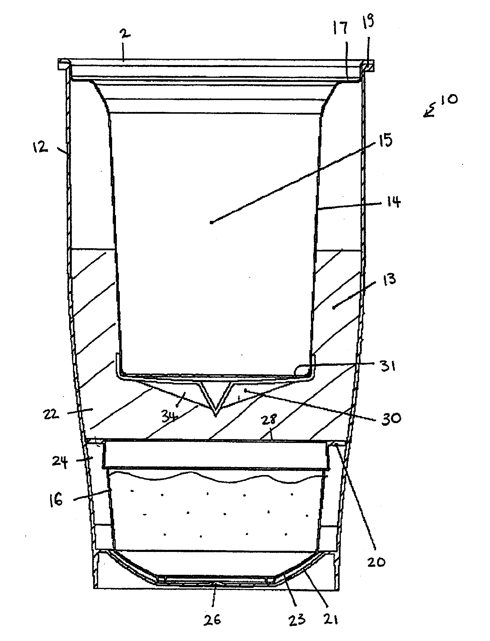
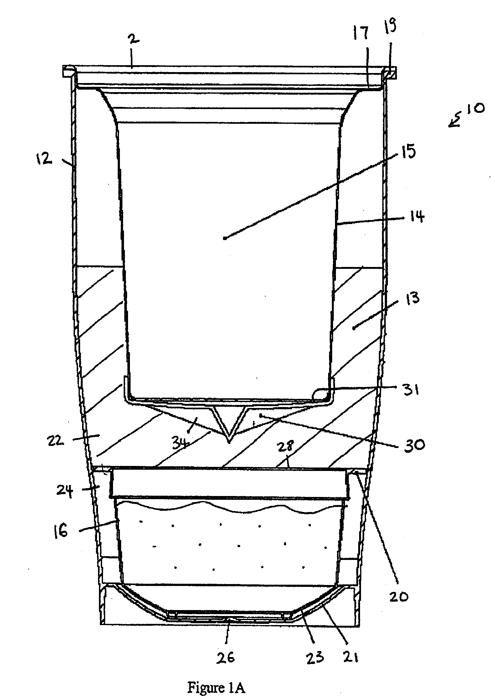
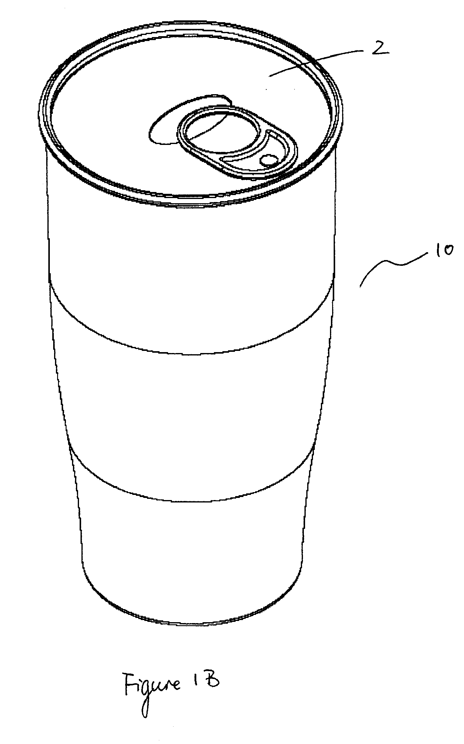
[0050] Referring to FIG. 1A, in one embodiment of the present invention, a container 10 includes an outer container body 12 defining a first chamber 13, an inner container body 14 defining a second chamber 15 disposed within the outer container body 12, and a reactant vessel 16 disposed within the first chamber 13. The inner container body 14 holds the beverage, food item, or other substance to be heated. A lid 2 covering the inner container body 14 maintains the substance inside the second chamber 15. It would be desirable to construct the inner container body 14 with a material having high thermal conductivity. For example, the inner container body 14 can be constructed of a metallic material such as aluminum or certain polymeric material such as polyolefin. In a preferred embodiment, the inner container body 14 defines a second chamber 15 which is able to hold liquid capacity of greater than 100 mL and in a more preferred embodiment, liquid capacity of greater than 200 mL of liqu...


PUM


Abstract

Various embodiments of the present invention feature a self-heating or self-cooling container that is simple in design. The container includes an outer container body, an inner container body, a reactant vessel, a breakable barrier, and a breaking device. The outer container body defines a first chamber and includes a first reactant. The inner container body defines a second chamber. The inner container body is disposed within the first chamber and hold a substance to be heated or cooled. The reactant vessel is provided within the first chamber underneath the inner container body. The reactant vessel contains a second reactant capable of reacting with the first reactant to generate an exothermic or endothermic reaction. The breakable barrier covers the reactant vessel. The breaking device is disposed within the first chamber between the inner container body and the reactant vessel. The breaking device is capable of breaking the barrier to release the second reactant into the first chamber to mix and react with the first reactant when activated.

Description

CROSS-REFERENCE [0001] This application claims priority to U.S. Provisional Application Ser. No. 60 / 736,485, entitled “Self-Heating Container”, filed Nov. 14, 2005, which is herein referenced and incorporated in its entirety.BACKGROUND [0002] 1. Field of the Invention [0003] The present invention relates to a container, and more particularly, to a self-heating container. [0004] 2. Background of the Invention [0005] For today's on-the-go consumer society, it would be convenient for consumers to be able to heat beverages, such as coffee, tea, or milk, and food products, such as soup, quickly without having access to any conventional source of heat. Consumers would be able to have hot cup of coffee anytime, anywhere regardless of whether there is a coffee maker, kettle, or a microwave. [0006] Self-heating technology has been around for a while. A typical self-heating technology employs an exothermic reaction using two reagents, where one reagent is a solid material such as calcium oxid...

Claims


Application Information

Patent Timeline
Patent Type & Authority Applications(United States)
IPC IPC(8): F24J1/00F24V30/00
CPCB65D17/163B65D81/3484B65D2517/0016F24J1/00F25D5/02F25D2331/805B65D17/4011F24V30/00
Inventor FORD, JOHN M.B.LUND, DOUGLAS M.
Owner HEAT WAVE TECH
Why Eureka
Try Eureka