Air conditioner cleaning apparatus and method

a technology for air conditioners and cleaning equipment, applied in lighting and heating equipment, stationary conduit assemblies, heating types, etc., to achieve the effect of reducing the discomfort of odour and potential health risks

Inactive Publication Date: 2007-06-07
NUTSOS MIKAEL
View PDF2 Cites 39 Cited by
  • Summary
  • Abstract
  • Description
  • Claims
  • Application Information

AI Technical Summary

Benefits of technology

[0009] The objective problem is to provide a method and an apparatus for reducing the discomfort of odour and potential health risks assoc

Problems solved by technology

The objective problem is to provide a method and an apparatus for reducing the discomfort of odour and potential health risks associate

Method used


Image

  • Air conditioner cleaning apparatus and method
  • Air conditioner cleaning apparatus and method
  • Air conditioner cleaning apparatus and method

Examples


Embodiment Construction

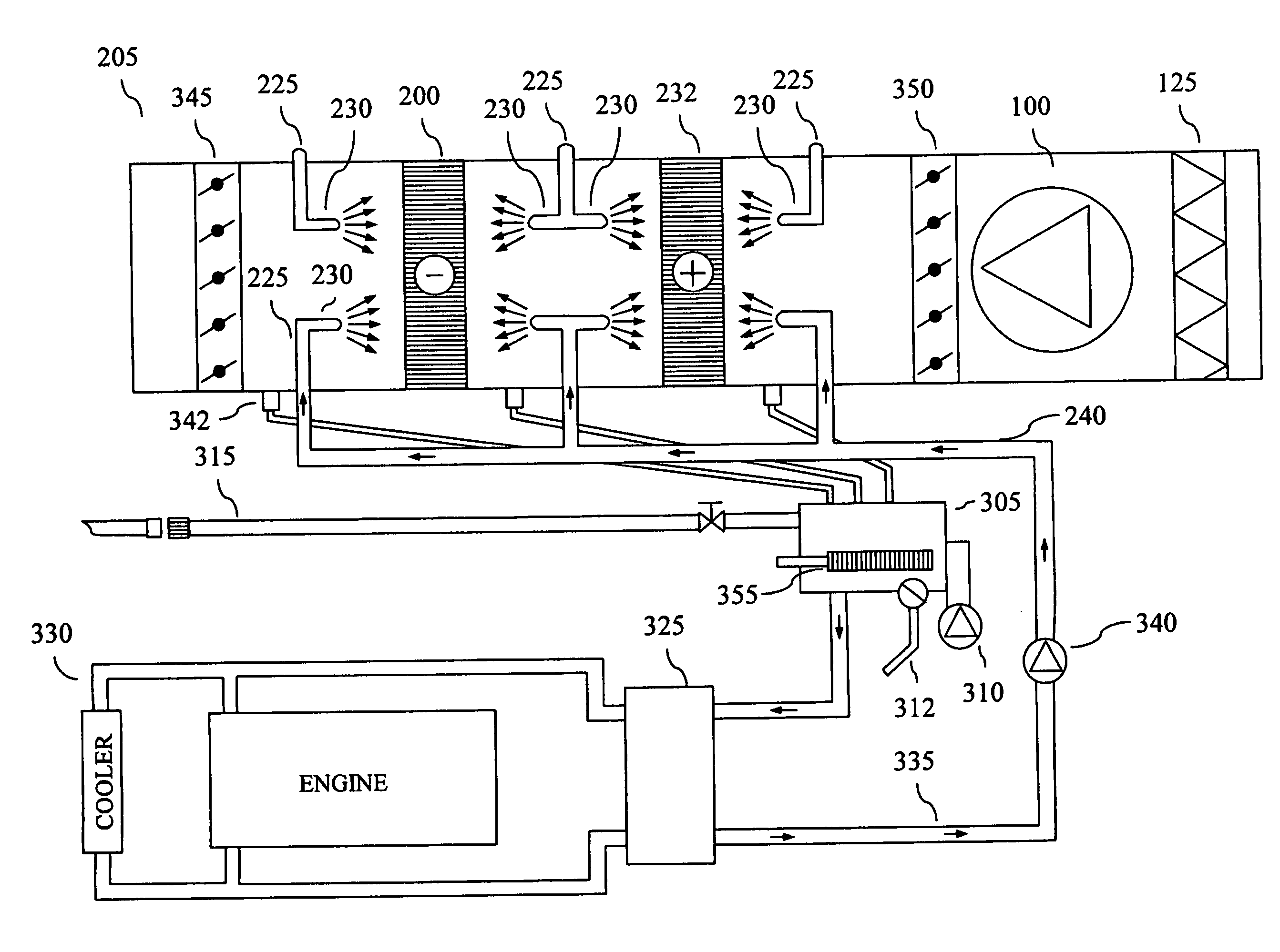
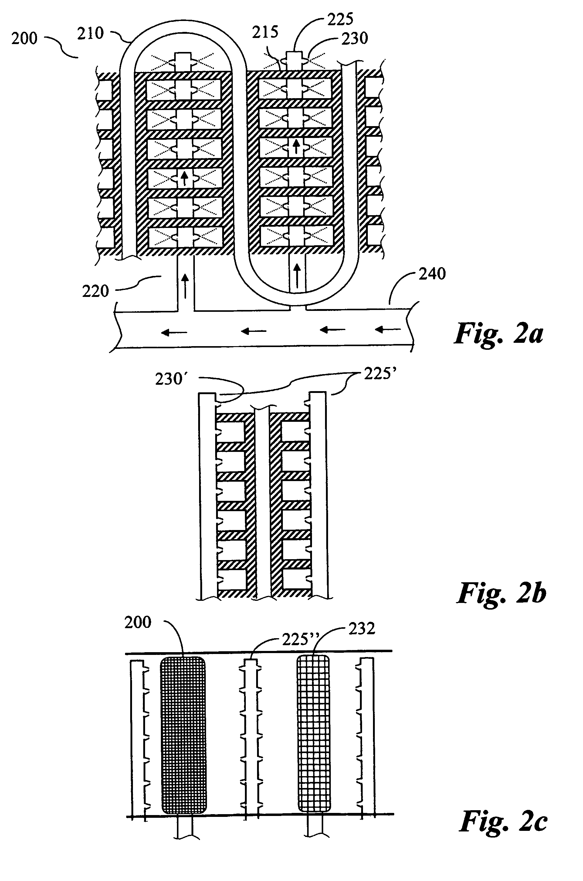
[0028] The principle of the present invention will be described with reference to the schematic illustration of FIGS. 2 and 3. Depicted in FIG. 2a is, in a cross-sectional frontal view, a cooling unit of an air conditioning unit. The cooling unit is realized by an evaporator 200 and contained in a housing (not shown). The housing typically also contain other functional parts of an air conditioning unit such as a fan, dampers and a heat radiator, which have for the reason of clarity been omitted in FIG. 2a. The evaporator 200 comprises of the evaporator coils 210 in which the cooling media flows. The evaporator coils 210 are preferably in a back and forth arrangement in order to provide a suitable length within a limited area. The evaporator coils are provided with cooling flanges 215, brazed or fastened by other means, to the evaporator coils 210. According to the invention a cleaning assembly 220 are provided within, on the surface of or adjacent to the evaporator 200. In a preferr...


PUM


Abstract

A cleaning apparatus, system and method for parts of the heating/cooling system of an vehicle. The apparatus effectively impedes odour and pollution originating from micro-organisms growing on the cooling and heating units. The cleaning assembly 220 includes of distribution tubes 225 provided with nozzles 230 arranged to spray cleaning substance onto the surfaces of the cooling and/or heating units 200, 232. The distribution tube preferably extends through at least a portion of the plurality of heating/cooling flanges 215 of the heating/cooling units and the nozzles are provided in the spaces formed between two adjacent flanges.

Description

[0001] The present invention relates to an air conditioner cleaning apparatus and method effectively impeding odour and pollution originating from an air conditioning system. In particular, the present invention relates to a cleaning apparatus suitable for use in an air conditioning system in a vehicle. BACKGROUND OF THE INVENTION [0002] An increasing number of vehicles are equipped with means for cooling the inlet air for the passenger compartment. The by far most common way of cooling the inlet air is by the use of an air conditioner, utilizing the refrigerating principles for cooling. In vehicles the air conditioner is typically assembled in connection with a fan and a heater radiator forming a heating / cooling system, or climate controller, for the interior of the vehicle. Schematically depicted in FIG. 1 is an example of a prior art vehicle heating / cooling system, comprising of a fan unit 100, a cooling unit 110 and a heating unit 120 provided in a common housing 130. Provided i...

Claims


Application Information

Patent Timeline
IPC IPC(8): F28G1/12B60H1/00B05B1/24B60HB60H3/00F28D1/047F28G9/00
CPCB60H1/00585B60H3/0085B60H3/0092F24F2003/1675F24F2221/225F28D1/0477F28D2021/0085F28D2021/0096F28G1/166F28G9/00F28F2265/20F28G15/003F24F8/24
Inventor NUTSOS, MIKAEL
Owner NUTSOS MIKAEL
Why Eureka
Try Eureka