
Display with multiple adjustable positions and angles

Inactive Publication Date: 2007-06-07
HANNSPREE INC
View PDF11 Cites 22 Cited by
  • Summary
  • Abstract
  • Description
  • Claims
  • Application Information

AI Technical Summary

Benefits of technology

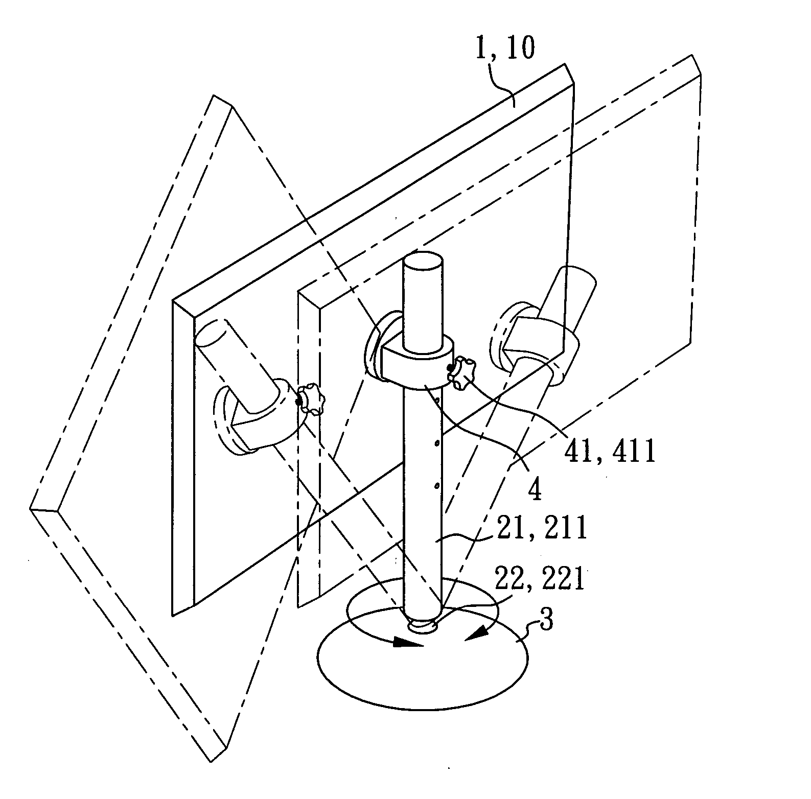
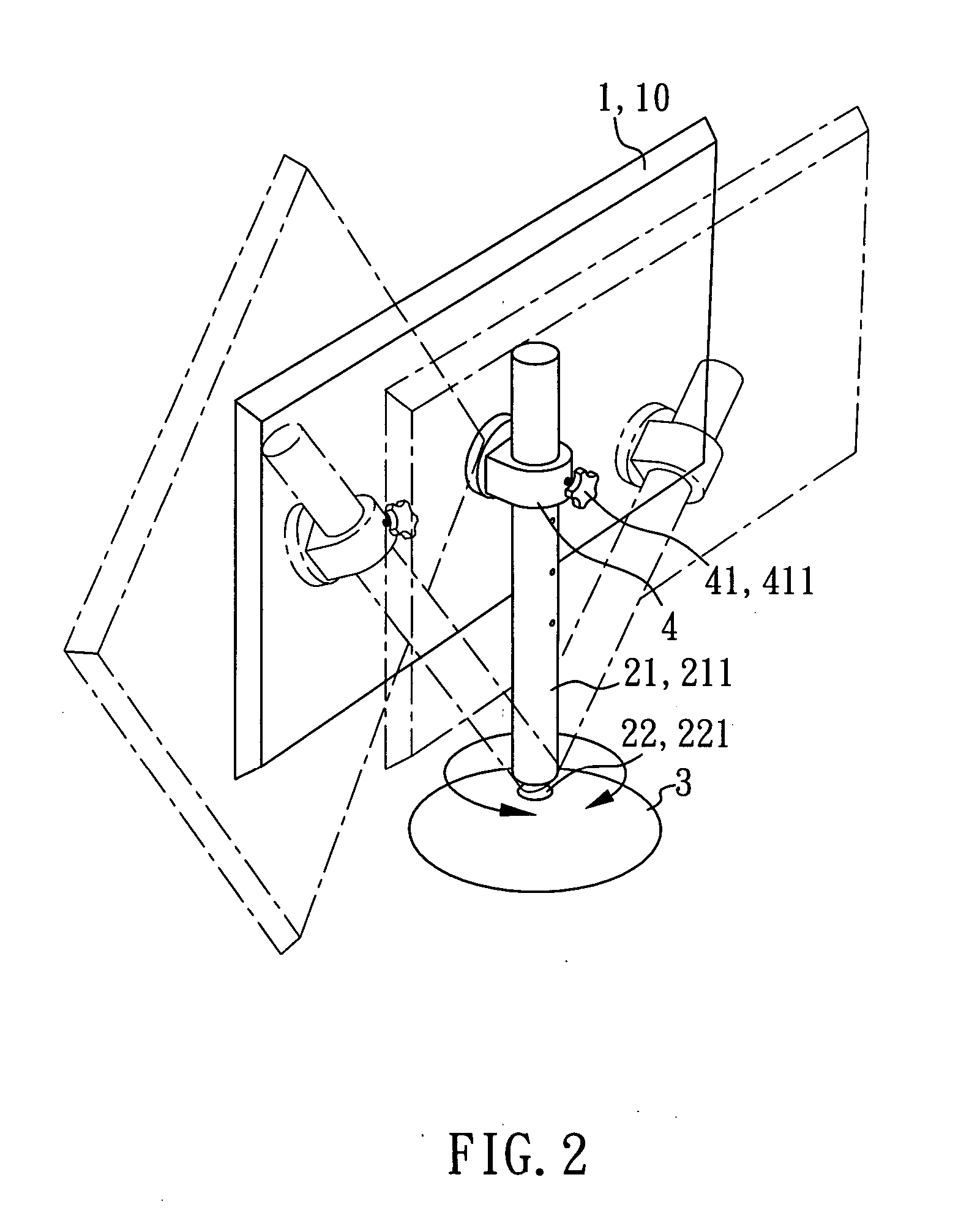
[0010] By means of the coupling structure between the universal joint of the post and the concave hole of the base, the user can adjust the direction and tilting angle of the screen subject to different requirements or different environments. The user can use single hand to hold the post and then to rotate or tilt the post relative to the base when adjusting the direction or tilting angle of the screen. Further, through the holder assembly, the user can conveniently adjust the height of the screen on the post. Further, the user can turn the screen about the pivot member at the holding member of the holder assembly clockwise or counterclockwise to the desired position.
[0013] Further, the post can be made having at least one gear rack fixedly provided at the periphery of the post body along the length, and the locking device of the holder assembly can be formed of at least one gear pivotally mounted in the holding member and respectively meshed with the at least one gear rack at the post body of the post to secure the holding member to the post body of the post by a friction force. This design allows the user to directly adjust the height of the holding member on the post body of the post with single hand.

Problems solved by technology

However, conventional pivot joints and hinge mechanisms for LCD commonly have a complex structure that is expensive to be manufactured.
When adjusting the tilting angle of the screen, the user must hold the base of the LCD with one hand and tilts the screen with the other hand thus this adjustment procedure is inconvenient.
It does not allow the user to adjust the tilting angle of the screen in different directions.

Method used


Image

  • Display with multiple adjustable positions and angles
  • Display with multiple adjustable positions and angles
  • Display with multiple adjustable positions and angles

Examples


Embodiment Construction

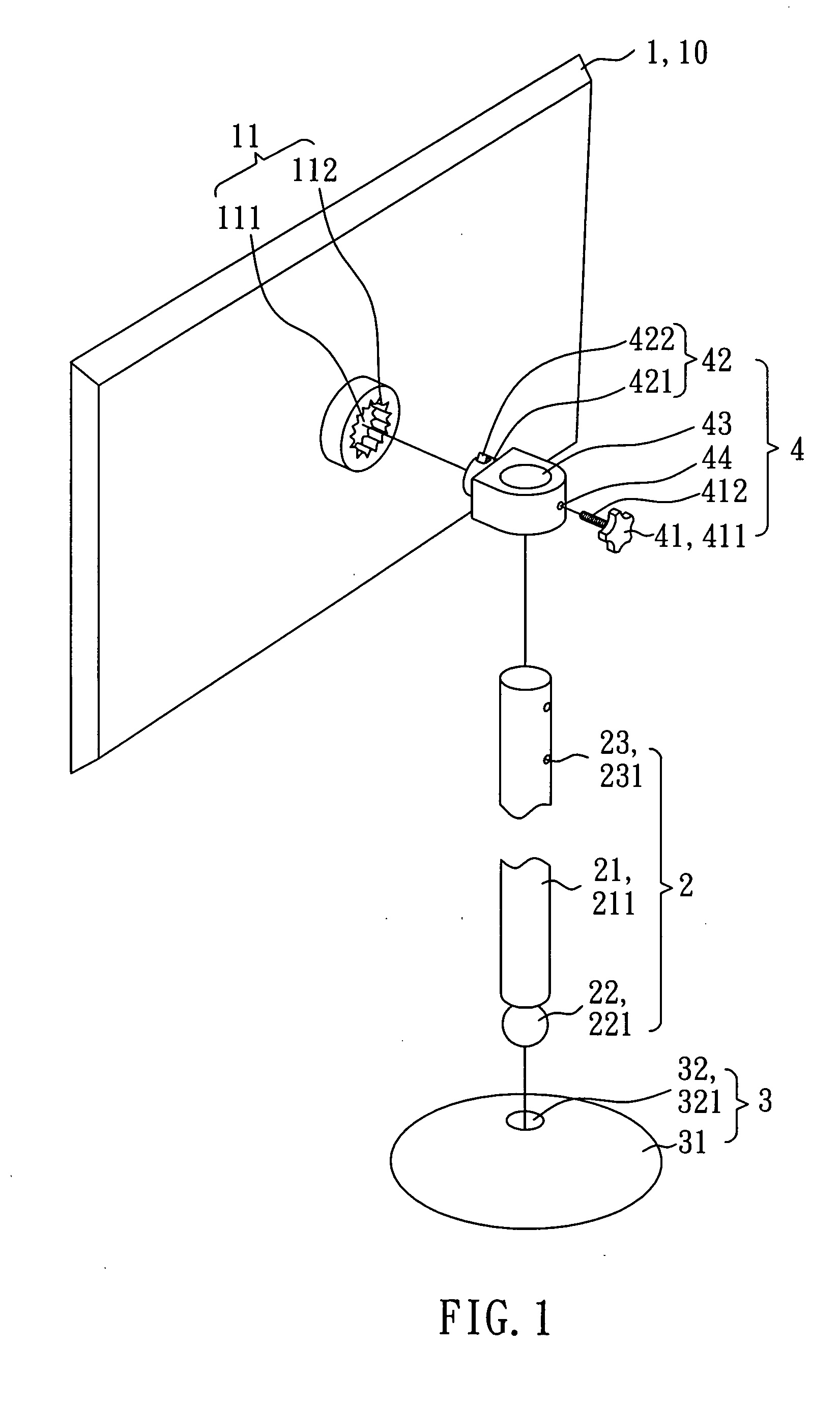
[0024] Referring to FIG. 1, a display in accordance with the first embodiment of the present invention is shown comprised of a screen 1, a post 2, a base 3, and a holder assembly 4.

[0025] The screen 1 according to this embodiment comprises an LCD 10 (Liquid Crystal Display), and a pivot unit 11 fixedly provided at the backside thereof. The pivot unit 11 has an axle hole 111, and a plurality of positioning grooves 112 equiangularly spaced around the inside wall of the axle hole 111. According to this embodiment, the quantity of the positioning grooves 112 is fifteen.

[0026] The base 3 has a top surface 31, and a top concave hole 32 is formed in the top surface 31. According to this embodiment, the top concave hole 32 forms a ball socket 321.

[0027] The post 2 comprises a post body 21, a universal joint 22, and a plurality-aligned of locating holes 23. The universal joint 22 is fixedly provided at the bottom end of the post body 21 and pivotally coupled to the top concave hole 32 of ...


PUM


Abstract

A display is disclosed to include a base, a post coupled to the base through a ball and socket joint for free adjustment at different angles, a holder assembly coupled and movable along the post, a locking device mounted in the holder assembly for locking the holder assembly to the post at the desired height, and a screen pivotally coupled to a pivot member at the holder assembly.

Description

BACKGROUND OF THE INVENTION [0001] 1. Field of the Invention [0002] The present invention relates to display devices and more particularly, to a flat-panel display that allows the user to conveniently adjust the direction and angle of the screen with single hand. [0003] 2. Description of Related Art [0004] Following rapid development of display manufacturing technology and mass production of liquid crystal displays (LCDs), such display devices have become intensively used to replace conventional CRT monitors and now dominate the market. [0005] An LCD has a liquid crystal cell positioned between two polarizers. An electric field is applied to the liquid crystal cell to make light pass through cell. The liquid crystal filled in the ell, therefore, is like a shutter, either allowing light to pass through or blocking the light. Therefore, the LCD has a certain range of visible angle and a preferable visual angle. An LCD must allow the user to conveniently adjust the viewing angle of the...

Claims


Application Information

Patent Timeline
IPC IPC(8): F16M11/00
CPCF16M11/105F16M11/14F16M11/2078F16M11/24F16M2200/028Y10S248/918Y10S248/919Y10S248/921Y10S248/923
Inventor LIOU, GUAN-DEHUANG, CHIA-PINELAI, LI-LITSAI, STEPHEN
Owner HANNSPREE INC
Learn More