El display apparatus and method for driving el display apparatus

Inactive Publication Date: 2007-06-07
TOSHIBA MATSUSHITA DISPLAY TECH
View PDF65 Cites 46 Cited by
  • Summary
  • Abstract
  • Description
  • Claims
  • Application Information

AI Technical Summary

Benefits of technology

[0063] By making the reset current Ia a current value of a predetermined value or more, the problem of insufficient writing in the low gradation region (low current region), which is a disadvantage of the current program system, does not occur.

Problems solved by technology

However, organic EL elements have a problem in that variations in the characteristics of the transistors of the polysilicon transistor array will cause display irregularities.
However in the voltage program system, charging and discharging capacity of a signal line is high in either a low gradation reg

Method used


Image

  • El display apparatus and method for driving el display apparatus
  • El display apparatus and method for driving el display apparatus
  • El display apparatus and method for driving el display apparatus

Examples


first embodiment

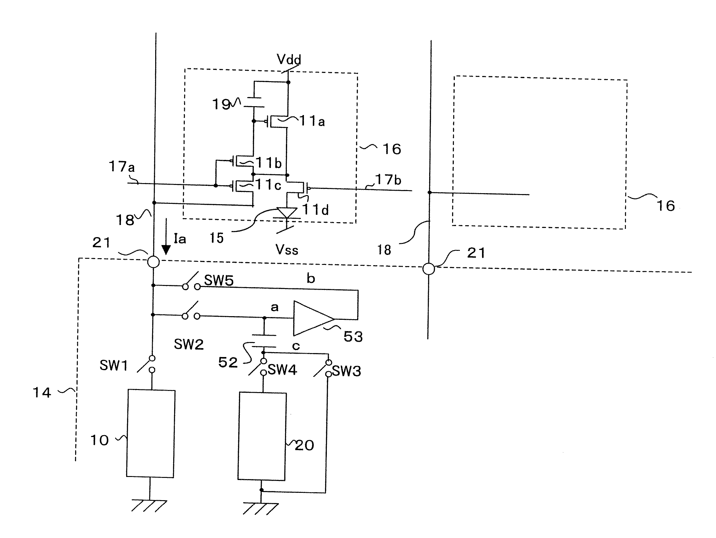
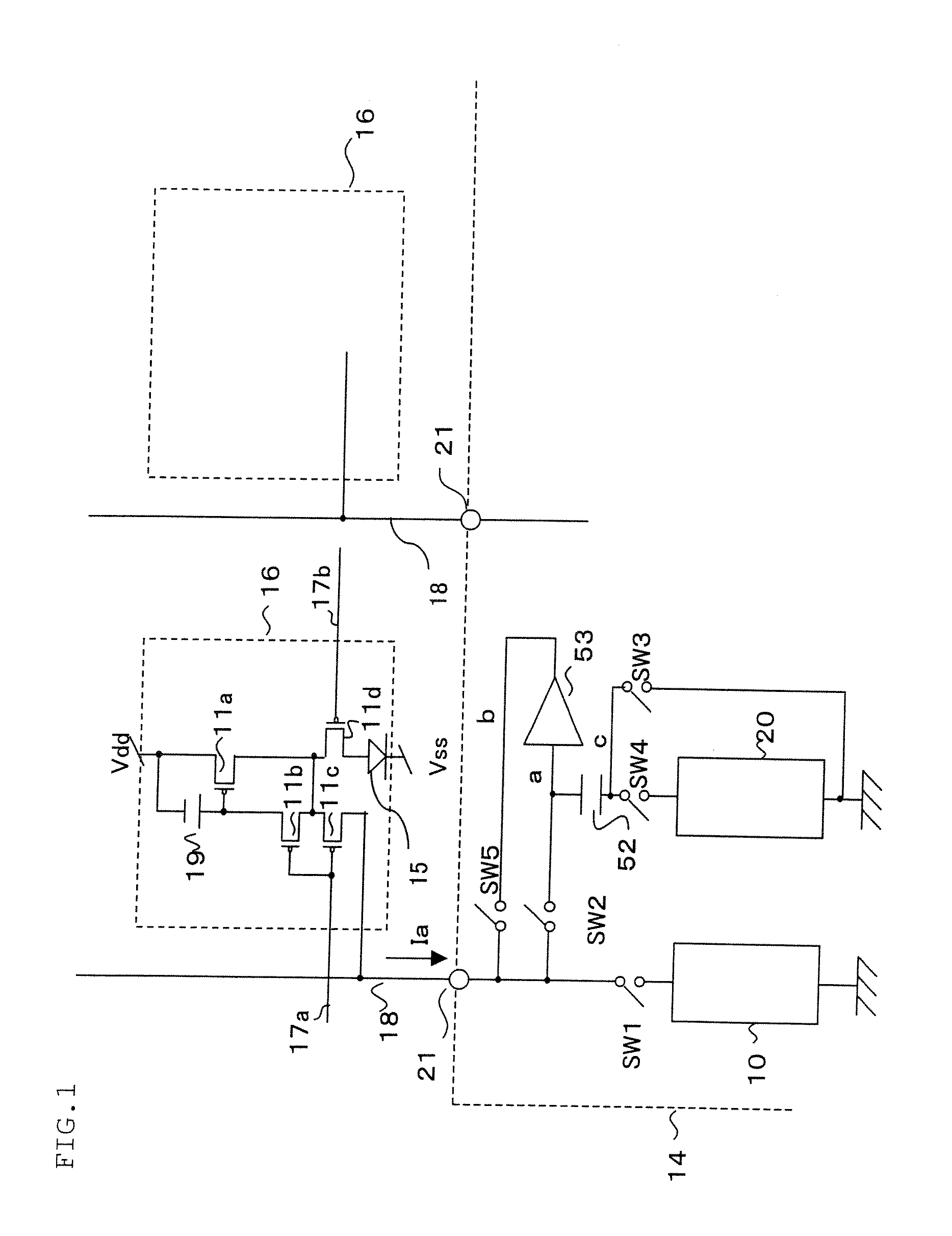
[0178]FIG. 1 is a schematic diagram of a driving circuit of an EL display apparatus of the present invention. An output terminal 21 of the source driver IC (circuit) 14 is connected to a source signal line 18. A plurality of pixels 16 are connected to each source signal line 18. An EL element 15 is formed on a pixel 16 and the pixels 16 are arranged in a matrix.

[0179] A constant current output circuit (current gradation circuit) 10 and a voltage gradation circuit 20 are configured or formed on each of the output terminals 21. The constant current output circuit 10 preferably outputs a gradation current such as a program current. In a first embodiment, however, the constant gradation output circuit 10 needs not to be able to output gradation current and only needs to output a predetermined constant current (program current).

[0180] By making it possible to output various amounts of constant current, the amount of the reset current Ia can be changed or altered according to the gradat...

second embodiment

[0377] A second embodiment of the present invention will be described below. In the embodiment below, description on the parts and the operations same as those of the first embodiment will be omitted. The description focuses on the differences from the first embodiment. The abovementioned description is applied to the embodiments hereafter. For example, a configuration relating to a driver circuit of FIG. 5, FIG. 6, FIG. 8, FIG. 9 and the like can be applied and combined as required. The configuration relating to the pre-charge methods such as in FIG. 12, FIG. 13, FIG. 14 and the like and the pre-charge circuit of FIG. 34 can be applied and combined as required. The configuration relating to the data transmitting method of FIG. 15 can be applied and combined as required. The configuration relating to the gate driver circuit of FIG. 20, the intermittent display of FIGS. 18A and 18B, FIGS. 21A and 21B, and FIGS. 22A and 22B, and the source driver circuit of FIG. 28, FIGS. 29A and 29B,...

third embodiment

[0397] The table shown in FIG. 44 shows an operation state of each component of a third embodiment of the present invention. With reference to FIG. 43 and FIG. 44, the third embodiment of the present invention will be described. Similarly to the second embodiment, the gradation voltage Vx will be described as V1.

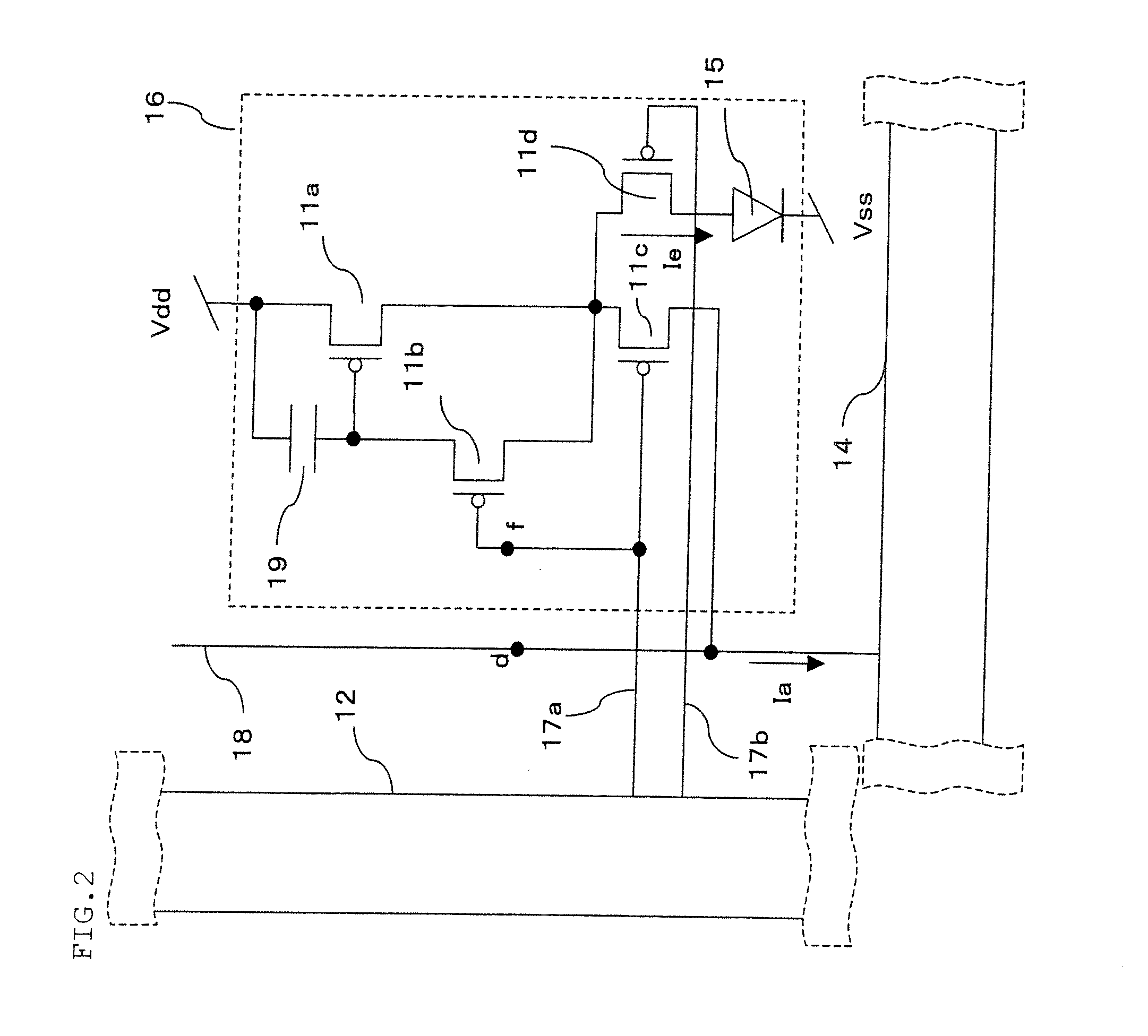
[0398] During the reset period, the gate driver circuit 12a controls the gate signal line 17a and selects one line of pixels. The transistors 11c and 11b of the selected line of pixels enter in the on state (closed). The source driver circuit 14 applies the reset current Ia to the source signal line 18a. The reset current Ia flows through the anode voltage Vdd→the driver transistor 11a→the transistor 11c→the source signal line 18a of the selected pixel 16. As described in the abovementioned embodiments, for the current direction of the reset current Ia, either the outlet current direction or the inlet current direction is selected and adopted according to a configuration of...


PUM


Abstract

An EL display apparatus in which pixels having EL elements are formed in a matrix, has a constant current circuit which generates a predetermined constant current; and a gradation voltage circuit which generates a gradation voltage; wherein the constant current generated by the constant current circuit is supplied to the pixels via a source signal line; and the gradation voltage generated by the gradation voltage circuit is supplied to the pixels via the source signal line.

Description

CROSS-REFERENCE TO RELATED APPLICATIONS [0001] This application claims priority to Japanese Patent Application No.2005-348486, filed in the Japanese Patent Office on Dec. 1, 2005, the entire contents of which are hereby incorporated herein by reference. BACKGROUND OF THE INVENTION [0002] 1. Field of the Invention [0003] The present invention relates to a driving method, driving circuits and a display apparatus of a self-luminous display panel (display apparatus) such as an EL display panel (display apparatus), which employs organic or inorganic electroluminescence (EL) elements or the like, and relates to a display panel (display apparatus) using the driving circuits. [0004] 2. Description of the Related Art [0005] An active-matrix image display apparatus using an organic electroluminescence (EL) material or an inorganic EL material as an electro-optic conversion material changes its emitting brightness according to a current written in pixels. The EL display panel is a self-luminou...

Claims


Application Information

Patent Timeline
IPC IPC(8): G09G3/30H05B44/00
CPCG09G3/3233G09G3/3241G09G3/325G09G3/3266G09G3/3283G09G2300/0417G09G2300/0819G09G2300/0842G09G2300/0852G09G2300/0861G09G2310/0205G09G2310/0248G09G2310/0289G09G2320/0233G09G2320/0261G09G2320/041G09G2330/028
Inventor NAKAMURA, NORIOTAKAHARA, HIROSHI
Owner TOSHIBA MATSUSHITA DISPLAY TECH
Why Eureka
Try Eureka