Optically transparent electromagnetic interference (EMI) shields for direct-view displays

a direct-view display and electromagnetic interference technology, applied in the field of optical systems and devices, can solve the problems of general loss of imaging light, display brightness, and plasma display panel emi emission, and achieve the effect of reducing the brightness of the display panel, and reducing the brightness

Inactive Publication Date: 2007-06-07
BRIGHT VIEW TECHNOLOGIES CORPORATION
View PDF17 Cites 43 Cited by
  • Summary
  • Abstract
  • Description
  • Claims
  • Application Information

AI Technical Summary

Benefits of technology

[0013] EMI shields according to various embodiments of the present invention that were described above may also be combined with conventional EMI shields that include a conductive mesh having an array of gaps therein, but that is free of an optical redirecting structure as was described above. In some embodiments, the conductive meshes include different ratios of gap area to mesh area. In other embodiments, one of the conductive meshes may consist of horizontally oriented conductors and the other of the conductive meshes may consist of vertically oriented conductors. In either case, the conductive mesh may comprise a base conductive layer, such as a plating base conductive layer, and an overlayer conductive layer, such as a plated conductive overlayer.

Problems solved by technology

Displays such as Cathode Ray Tube (CRT) and plasma display panels can produce undesirable EMI emissions that generally must be reduced to levels dictated by various regulatory agencies such as the Federal Communications Commission (FCC).
A major potential drawback common to these types of construction is the general loss of imaging light, or display brightness, caused by the EMI shield.
Conventional conductive materials such as copper or aluminum are not transparent to visible light and therefore block some of the display light, resulting in loss of brightness.
Transparent conductors such as Indium Tin Oxide (ITO) can provide conductivity without impairing visible transmission, but the conductivity of this material is generally relatively low and it is generally very expensive compared to common metals.

Method used


Image

  • Optically transparent electromagnetic interference (EMI) shields for direct-view displays
  • Optically transparent electromagnetic interference (EMI) shields for direct-view displays
  • Optically transparent electromagnetic interference (EMI) shields for direct-view displays

Examples


Embodiment Construction

[0023] The present invention now will be described more fully hereinafter with reference to the accompanying drawings, in which embodiments of the invention are shown. However, this invention should not be construed as limited to the embodiments set forth herein. Rather, these embodiments are provided so that this disclosure will be thorough and complete, and will fully convey the scope of the invention to those skilled in the art. In the drawings, the thickness of layers and regions may be exaggerated for clarity. Like numbers refer to like elements throughout. As used herein the term “and / or” includes any and all combinations of one or more of the associated listed items and may be abbreviated as “ / ”.

[0024] The terminology used herein is for the purpose of describing particular embodiments only and is not intended to be limiting of the invention. As used herein, the singular forms “a,”“an” and “the” are intended to include the plural forms as well, unless the context clearly indi...


PUM


Abstract

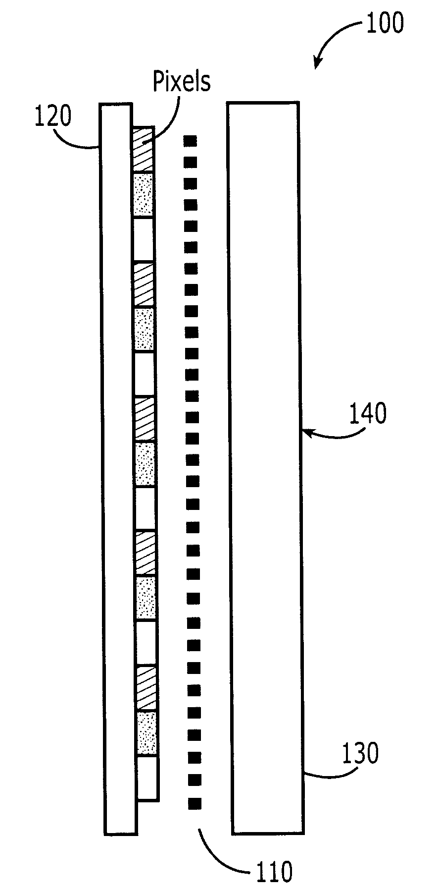
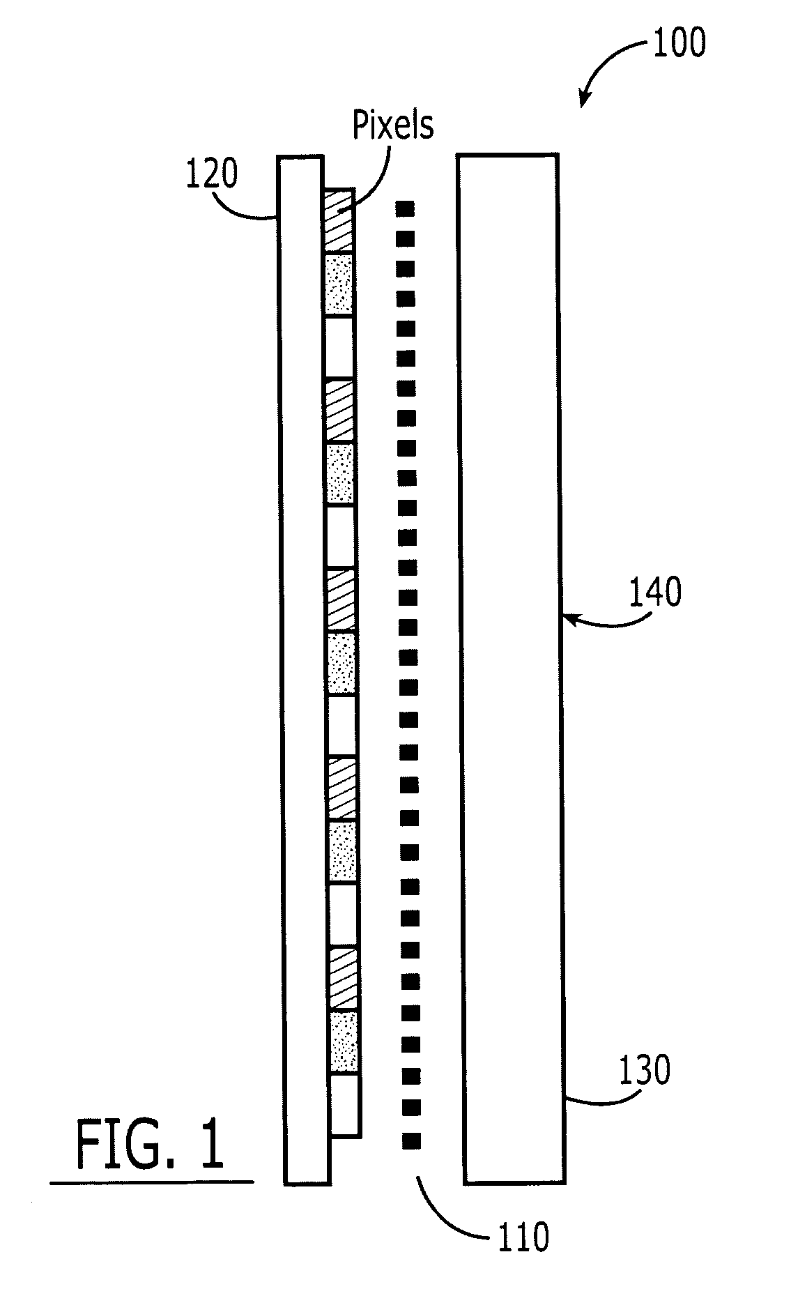
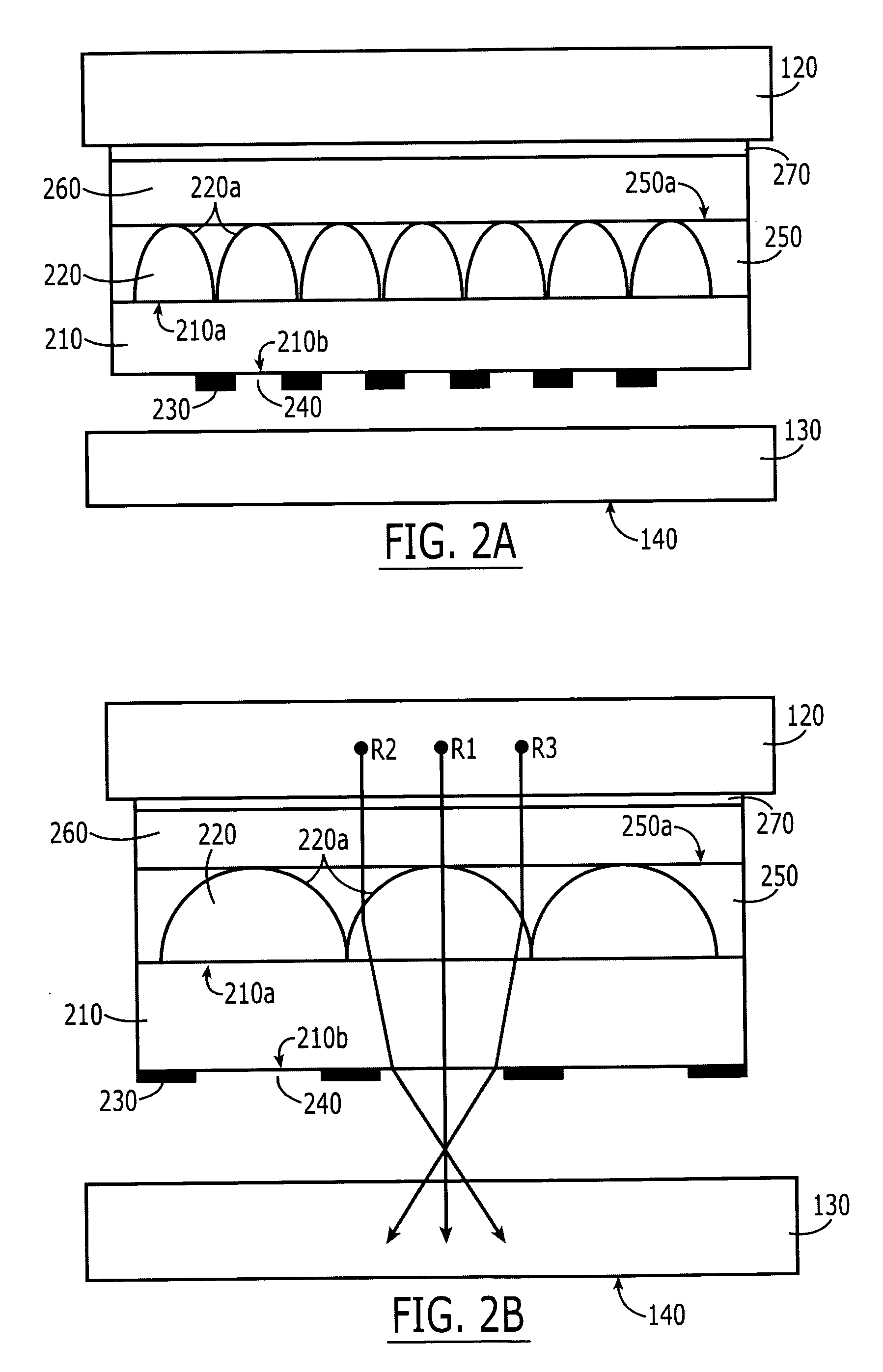
Electromagnetic Interference (EMI) shields for a direct-view display having a direct-view display panel and an outer panel that provides an outer surface for the direct-view display. These EMI shields include a conductive mesh having an array of gaps therein. The conductive mesh is configured to shield at least some of the EMI that is emitted by the direct-view display panel. An optical redirecting structure is also included, that is configured to redirect at least some optical radiation that is emitted from the direct-view display panel that would strike the conductive mesh, through the gaps in the conductive mesh. The EMI shield is configured to mount between the direct-view display panel and the outer panel such that the optical redirecting structure is adjacent the direct-view display panel and the conductive mesh is remote from the direct-view display panel.

Description

CROSS-REFERENCE TO RELATED APPLICATION [0001] This application is a continuation-in-part (CIP) of application Ser. No. 11 / 364,423, filed Feb. 28, 2006, entitled Contrast Enhancement Films for Direct-View Displays and Fabrication Methods Therefor, which itself claims the benefit of provisional application Ser. No. 60 / 748,271, filed Dec. 7, 2005 entitled Contrast Enhancement Films for Direct-View Displays and Fabrication Methods Therefor. All of the above applications are assigned to the assignee of the present application, the disclosures of which are hereby incorporated herein by reference in their entirety as if set forth fully herein.FIELD OF THE INVENTION [0002] This invention relates to optical systems, devices, processes and fabrication methods, and more particularly to Electromagnetic Interference (EMI) shields, systems and operations using same, and methods of fabricating same. BACKGROUND OF THE INVENTION [0003] Electromagnetic Interference shields, also referred to as EMI sh...

Claims


Application Information

Patent Timeline
Patent Type & Authority Applications(United States)
IPC IPC(8): G02B27/10
CPCH01J11/10H01J11/44H01J29/867H01J31/123H01J2211/446H01J2329/869H05K9/0054
Inventor WOOD, ROBERT L.REED, DAVID L.
Owner BRIGHT VIEW TECHNOLOGIES CORPORATION
Why Eureka
Try Eureka