
System and method for range measurement of a preceding vehicle

a vehicle and system technology, applied in the field of vehicle system and method for range and lateral position measurement of a preceding vehicle, can solve the problems of difficult to maintain accuracy, difficult to identify objects, and high cost of millimeter wave type radar systems such as 77 ghz systems, so as to improve object recognition capability and robust range

Inactive Publication Date: 2007-06-07
VISTEON GLOBAL TECH INC
View PDF84 Cites 37 Cited by
  • Summary
  • Abstract
  • Description
  • Claims
  • Application Information

AI Technical Summary

Benefits of technology

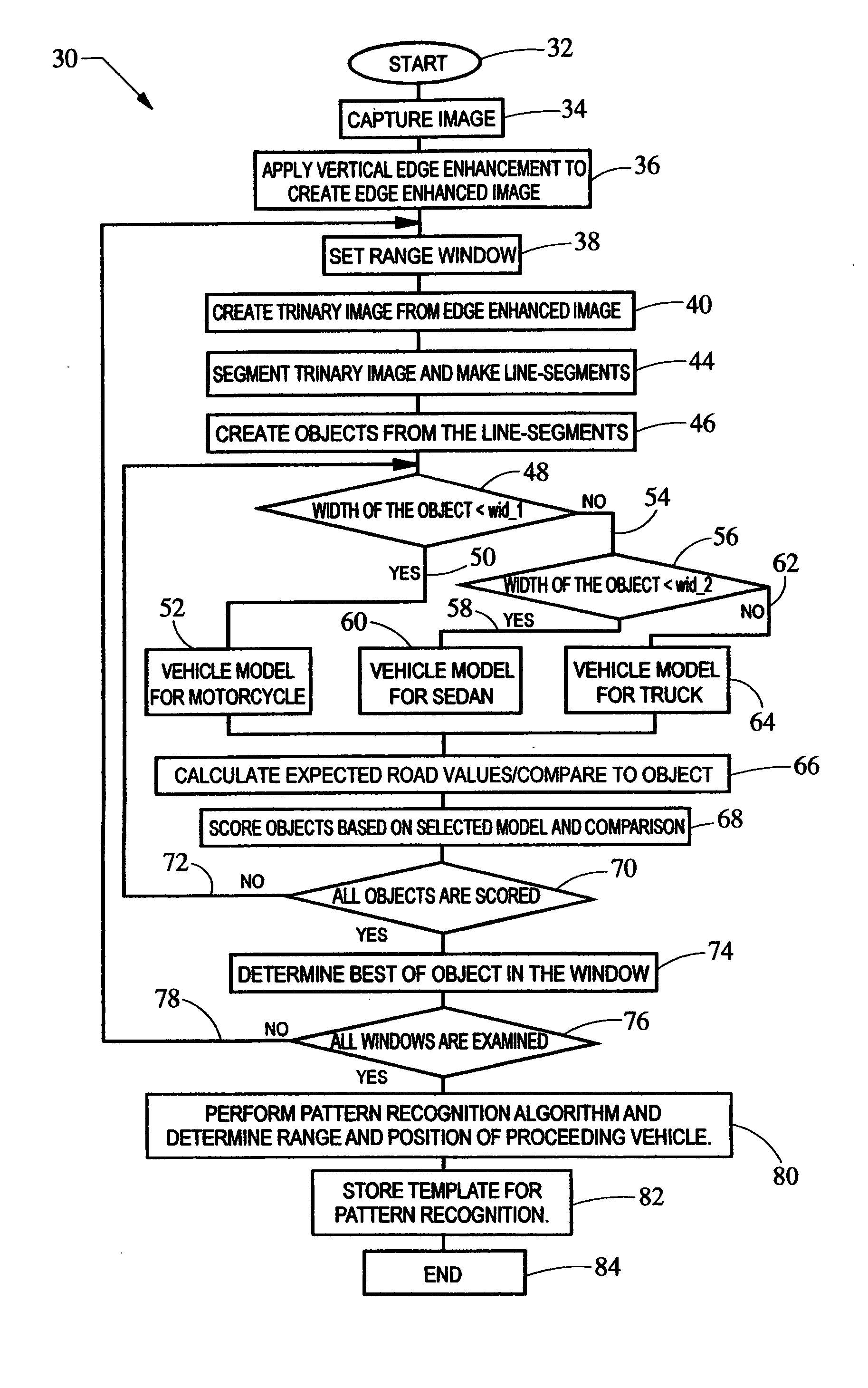
[0011] In order to complement the range-window analysis, a pattern matching analysis is also performed. A template image is stored based on the range window algorithm. The template may be used in subsequent images to perform a pattern matching, such as a cross correlation. The results of the cross correlation may be combined with or substituted for the results of the range window algorithm to provide more robust range and lateral position measurements of the preceding vehicle. The analysis described above is referred to herein as pattern matching analysis. The combination of the pattern matching analysis and the range-window analysis provides a system with improved object recognition capability.

Problems solved by technology

However, millimeter wave type radar systems such as 77 GHz systems are typically quite expensive.
Further, radar, while good for range determination is generally, not well suited to identify the object and give an accurate lateral position.
However, these systems are typically difficult to maintain the accuracy due to the accurate alignment required between the two cameras.
They are also expensive requiring two image processors, twice as many image processors as a single camera system.
Further, both conventional camera and radar systems can be easily confused by multiple objects in an image.
In addition, brightness variation in the background of the image, like the shadows of vehicles and roadside objects, can also increase the difficulty for these systems to identify the vehicle.
In view of the above, it can be seen that conventional ACC or LSF systems may have difficulty identifying vehicles due to a complex background environment.
As noted above, the electrical image includes many characteristics that make preceding vehicles difficult to identify.

Method used


Image

  • System and method for range measurement of a preceding vehicle
  • System and method for range measurement of a preceding vehicle
  • System and method for range measurement of a preceding vehicle

Examples


Embodiment Construction

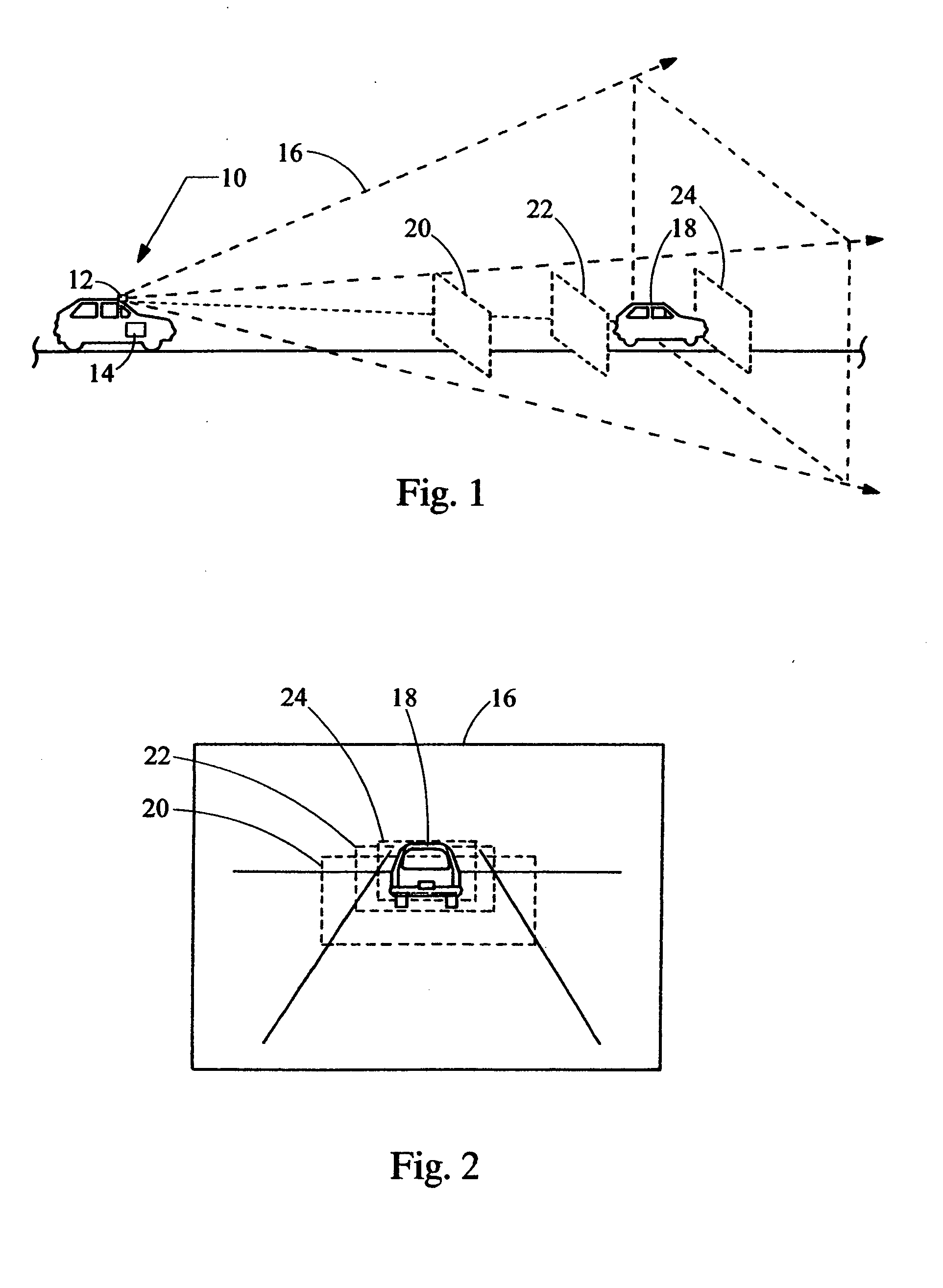
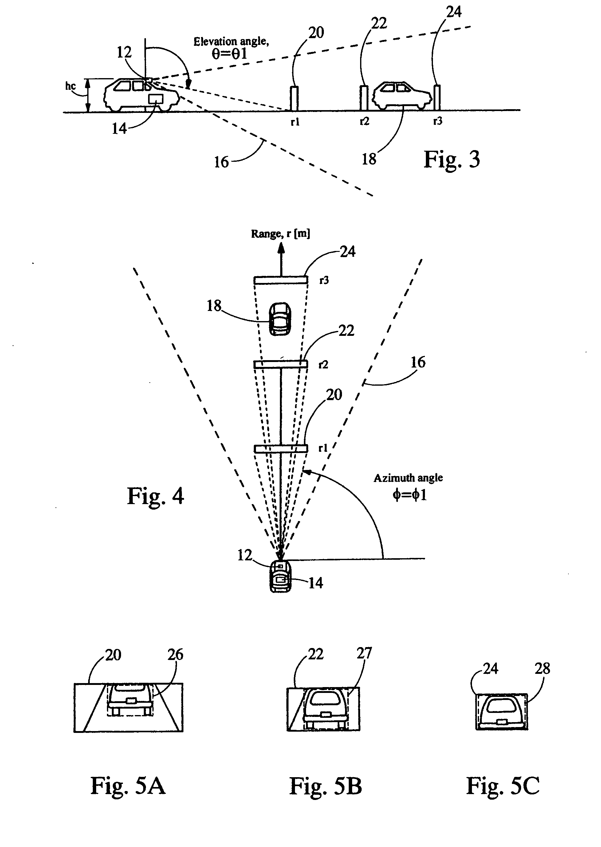
[0043] Referring now to FIG. 1, a system embodying the principles of the present invention is illustrated therein and designated at 10. As its primary components, the system 10 includes a single camera 12 and a processor 14. The camera 12 is located so as to be able to collect an optical image of a region of interest 16 including a vehicle 18. One such location is in the housing of the rearview mirror. The optical image received by the camera 12, is converted to an electrical image that is provided to the processor 14.

[0044] The electrical image includes many characteristics that make preceding vehicles difficult to identify. Multiple techniques may be employed to identify the preceding vehicle. With the system and method of the present invention the processor 14 is configured to store a template, such as a portion of edge-enhanced image, of the preceding vehicle in a previous image. The template may be, preferably, identified using a range window algorithm as described herein, alt...


PUM


Abstract

A system for determining range and lateral position of a vehicle is provided. The system includes a camera and a processor. The camera is configured to view a region of interest, including the vehicle, and generate an electrical image of the region. The processor is in electrical communication with the camera to receive the electrical image and analyzes the image by performing a pattern matching algorithm on the electrical image, based on a template. A score is determined based on the algorithm indicating the likelihood that certain characteristics of the electrical image actually correspond to the vehicle.

Description

BACKGROUND [0001] 1. Field of the Invention [0002] The present invention generally relates to a system in a vehicle and method for range and lateral position measurement of a preceding vehicle on the road. [0003] 2. Description of Related Art [0004] Radar and stereo camera systems for adaptive cruise control (ACC), have been already introduced into the market. Recently, radar has been applied to pre-crash safety system, collision avoidance and low speed follower (LSF) systems. Typically, the range and lateral position measurement of a preceding vehicle is accomplished utilizing radar and / or stereo camera systems. Radar systems can provide a very accurate range. However, millimeter wave type radar systems such as 77 GHz systems are typically quite expensive. Laser radar is low cost, but requires mechanical scanning. Further, radar, while good for range determination is generally, not well suited to identify the object and give an accurate lateral position. [0005] Stereo camera system...

Claims


Application Information

Patent Timeline
IPC IPC(8): G06K9/00G06K9/64
CPCG01C3/08G06K9/3241G06K9/00805G06T7/0044G06T2207/30248G06K2209/23G06T7/74G06V20/58G06V10/255G06V2201/08G06T7/70G01S11/12
Inventor MIYAHARA, SHUNJI
Owner VISTEON GLOBAL TECH INC
Learn More