Image forming apparatus

a technology of forming apparatus and forming tube, which is applied in the direction of electrographic process apparatus, instruments, optics, etc., can solve the problem of virtually impossible to form an imag

Active Publication Date: 2007-06-07
CANON KK
View PDF25 Cites 30 Cited by
  • Summary
  • Abstract
  • Description
  • Claims
  • Application Information

AI Technical Summary

Benefits of technology

[0005] According to an aspect of the present invention, there is provided an image forming apparatus comprising toner image forming means for forming a having chromatic toner image a transparent toner image; fixing means for heating and fixing the non-transparent toner image and the transparent toner image on recording material; glossiness detecting means for detecting a glossiness of an area in which the non-transparent toner image and the transparent toner image are overlaid and fixed; control means for controlling an amount of the transparent toner, per unit area, on the recording material on the basis of a result of detection by said detecting means.
[0006] According to another aspect of the present invention, there is provided an image forming apparatus comprising toner image forming means for forming a non-transparent toner image and the transparent toner image on a recording material; fixing means for heating and fixing the non-transparent toner image and the transparent toner image on recording material; non-transparent toner image detecting means for detecting the non-transparent toner image fixed on the recording material by said fixing means; non-transparent toner amount control means for controlling a non-transparent toner amount, per unit area, on the recording material on the basis of a result of detection by said non-transparent toner image detecting means; glossiness detecting means for detecting a glossiness of an area in which the toner amount is controlled by said non-transparent toner amount control means and in which the non-transparent toner image and the transparent toner image are overlaid and fixed; transparent toner amount control means for controlling a toner amount, per unit area, of the transparent toner on the recording material on the basis of a result of detection by said glossiness detecting means.

Problems solved by technology

However, an image forming apparatus, such as the above described one, which heats the toner on recording medium to fix the toner to the recording medium suffers from the following problem.
Thus, it has been virtually impossible to form an image, the glossiness of which on recording medium is exactly at a desired level after the recording medium is heated for the fixation.

Method used


Image

  • Image forming apparatus
  • Image forming apparatus
  • Image forming apparatus

Examples


embodiment 1

[Structure]

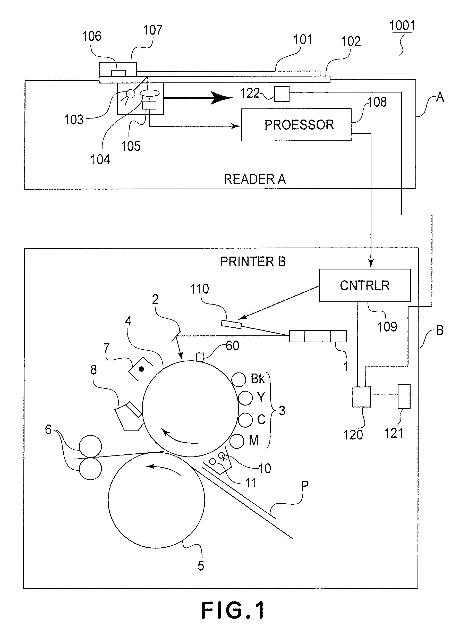
[0038]FIG. 1 is a schematic drawing of the image processing apparatus 1001, showing the general structure of the apparatus 1001.

[Reader Section]

[0039] An original 101 is placed on an original placement glass platen 102 of a reader section A, and is illuminated by a light source 103. The light reflected by the original 101 is focused on a CCD image sensor 105 (color image detecting means) through an optical system 104. The CCD image sensor 105 is made up of three groups of CCDs, which are the group for red color, group for green color, and group for blue color, in which the CCDs are arranged in a straight line. The CCD groups for the red, green, and blue colors generate picture signals corresponding to the primary color components of the original. The optical reading unit converts the optical image of the original 101 into sequential electrical signals, as it is moved in the direction indicated by an arrow mark in FIG. 1.

[0040] The optical reading unit is provided with...

embodiment 2

[0154] In the first embodiment described above, the image forming apparatus was designed so that a toner image formed on the photosensitive drum 4 is directly transferred onto the recording medium P borne on the transfer drum 5. However, the present invention is also applicable to an image forming apparatus designed so that multiple monochromatic color toner images, different in color, and a transparent toner image, are formed in layers on the photosensitive drum 4, and then, are directly transferred onto recording medium, as it is to the image forming apparatus in the first embodiment. This embodiment also can achieve the same beneficial effects as those achieved by the first embodiment.

[0155]FIG. 28 shows an example of such an image forming apparatus. Like the image forming apparatus in the first embodiment, the image forming apparatus 1002 shown in FIG. 28 is made up of a reader section A and printer section B. The reader section A of the image forming apparatus 1002 is the same...

embodiment 3

[0166] In the first embodiment described above, the image forming apparatus was designed to transfer a toner image formed on the photosensitive drum 4, onto the recording medium P borne on the transfer drum 5. Further, in the second embodiment, the image forming apparatus was designed to transfer a multilayer toner image formed on the photosensitive drum 4, onto the recording medium P. However, the present invention is also applicable to an image forming apparatus of the so-called intermediary transfer type, that is, an image forming apparatus in which a toner image formed on the photosensitive drum 4 is temporarily transferred onto an intermediary transferring member as the second image bearing member, and then, is transferred from the intermediary transferring member, onto the recording medium P. That is, an image forming apparatus of the intermediary transfer type can also benefit from the present invention as can the image forming apparatus in the first and second embodiments. F...


PUM


Abstract

An image forming apparatus including toner image forming means for forming a having chromatic toner image a transparent toner image; fixing means for heating and fixing the non-transparent toner image and the transparent toner image on recording material; glossiness detecting means for detecting a glossiness of an area in which the non-transparent toner image and the transparent toner image are overlaid and fixed; control means for controlling an amount of the transparent toner, per unit area, on the recording material on the basis of a result of detection by the detecting means.

Description

FIELD OF THE INVENTION AND RELATED ART [0001] The present invention relates to an image forming apparatus, such as an electrophotographic copying machine, printer, etc. In particular, it relates to a color image forming apparatus which forms a toner image on recording medium using a combination of color toner and transparent toner, and thermally fixes the toner image to the recording medium. [0002] Generally, the glossiness level at which an electrophotographic image forming apparatus, such as the abovementioned one, in accordance with the prior art, forms an image is determined by the total amount of toner (color toner and transparent toner) deposited on a recording medium. Therefore, in order to control the glossiness level (after thermal fixation) at which the image forming apparatus forms an image, the amount by which transparent toner is deposited on a recording medium, per unit area, is controlled according to the total amount by which the color toners are deposited on the rec...

Claims


Application Information

Patent Timeline
Patent Type & Authority Applications(United States)
IPC IPC(8): G03G15/08
CPCG03G15/5062G03G15/6585G03G2215/00805
Inventor ZAIMA, NOBUHIKO
Owner CANON KK
Why Eureka
Try Eureka