Helical stent

a helical stent and helical stent technology, applied in the field of helical stents, can solve the problems of untreated aneurysms that are susceptible to rupture, structures requiring a large open area are not expected to be effective, and the structure requiring a large open area is risky and expensive, so as to shorten the pitch (distance per turn) of the helical elements

Active Publication Date: 2007-06-07
FLEXIBLE STENTING SOLUTIONS
View PDF84 Cites 127 Cited by
  • Summary
  • Abstract
  • Description
  • Claims
  • Application Information

AI Technical Summary

Benefits of technology

[0011] The present invention relates to a stent providing a high percentage of vessel coverage, preferably at least about 50% of the portion of the vessel covered by the helical elements of the stent. The stent comprises helical elements interposed between strut members in which the helical elements are connected to the strut members by linking elements. The strut members provide radial structure of the stent and an anchoring mechanism. The portion of the stent having helical elements provides a high percentage of covered area for example, in an aneurysm area. The linking elements provide part of a mechanism that allo

Problems solved by technology

Untreated aneurysms are susceptible to rupture.
Clipping is very invasive, risky and expensive.
This type of structure requiring a large o

Method used


Image

  • Helical stent
  • Helical stent
  • Helical stent

Examples


Embodiment Construction

[0035] Reference will now be made in greater detail to a preferred embodiment of the invention, an example of which is illustrated in the accompanying drawings. Wherever possible, the same reference numerals will be used throughout the drawings and the description to refer to the same or like parts.

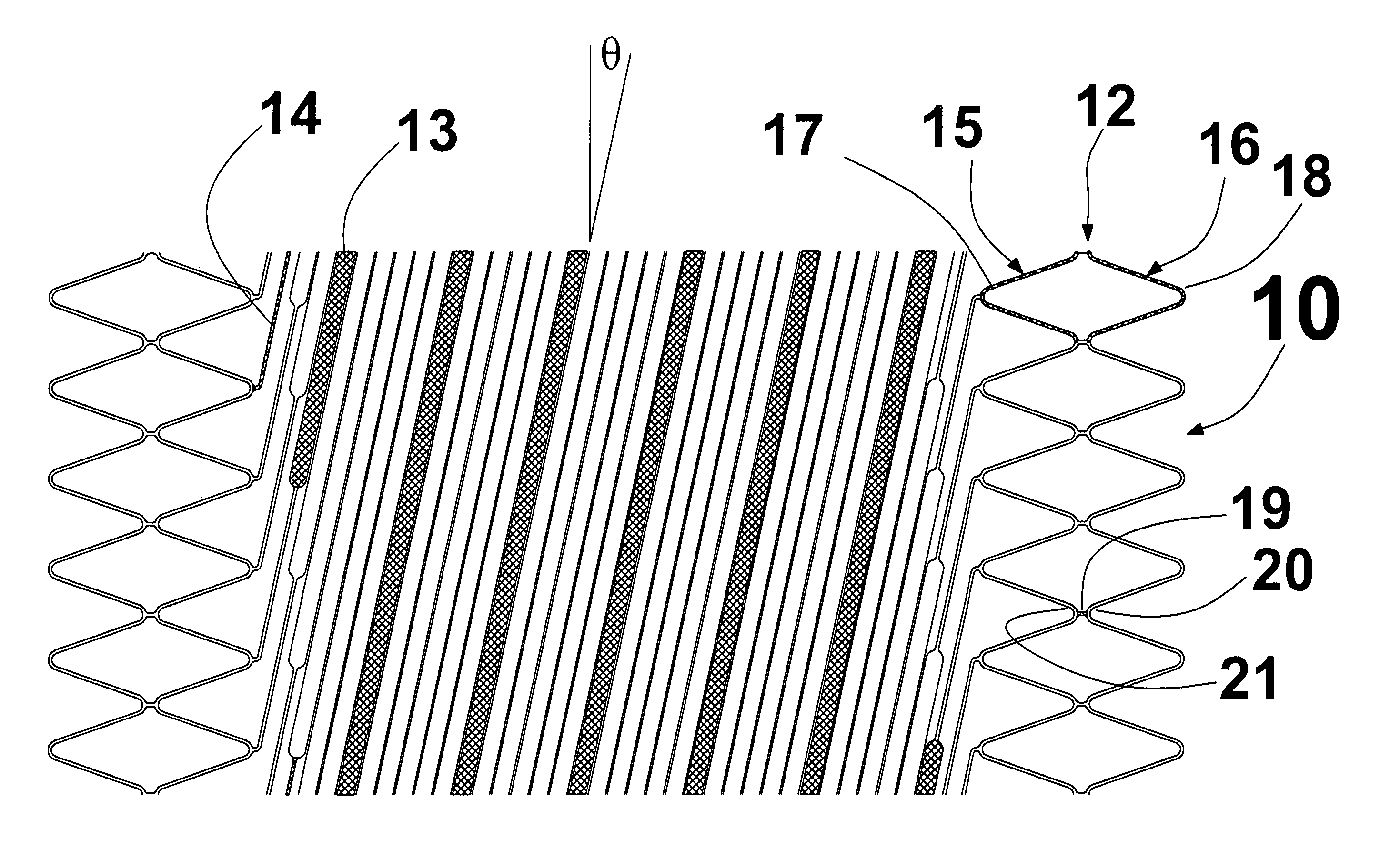
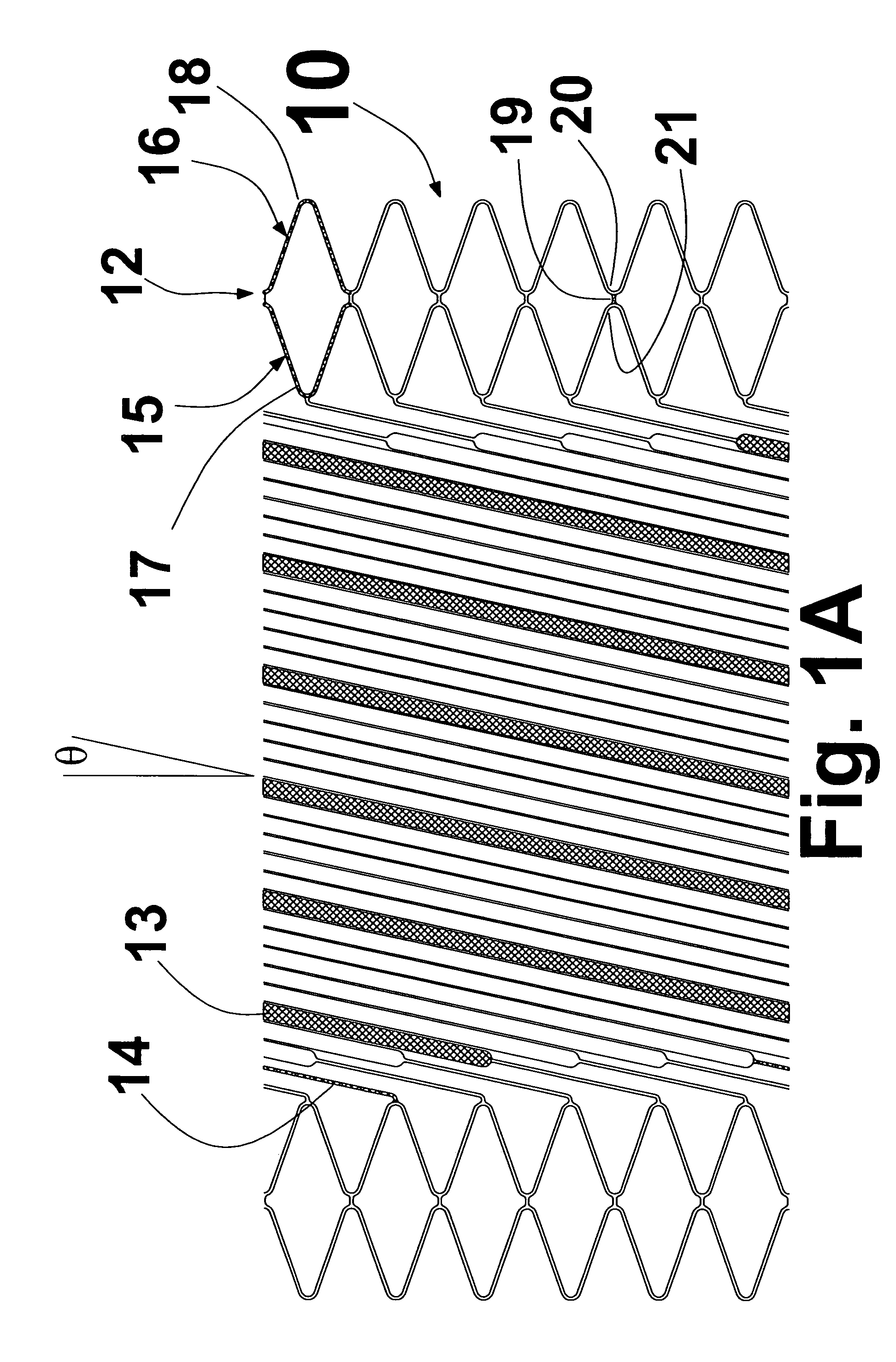
[0036]FIG. 1A is a plan view of a first embodiment of stent 10. As used herein, the term plan view will be understood to be a 2 dimensional (2-D) view where the stent has been cut along the axis and laid out flat, such that the bottom edge could be wrapped around a cylinder and connected to the top edge. Unless otherwise indicated all plan views are plan views of the stent in an expanded state. Stent 10 comprises strut members 12, helical elements 13 and flexible linking elements 14. In this representation one of helical elements 13 has been shaded. Strut members 12 comprise one or more strut ring portions 15 and 16. Strut ring portions 15 and 16 comprise respectively a plurality of stru...


PUM


Abstract

The present invention relates to a stent providing a high percentage of vessel coverage, preferably at least about 50% of the portion of the vessel covered by the helical elements of the stent. The stent comprises helical elements interposed between strut members in which the helical elements are connected to the strut members by linking elements. The portion of the stent having helical elements provides a high percentage of covered area for example, in an aneurysm area. The linking elements provide part of a mechanism that allows vessel coverage to be maintained as the stent is deployed from a crimped state to an expanded state allowing the helical elements to change its helix angle (the angle at which the helical elements progresses around the circumference and along the length of the stent) and thereby the pitch of the helical elements as the stent is expanded.

Description

CROSS REFERENCE TO RELATED APPLICATION [0001] This application claims the benefit of U.S. Provisional Patent Application No. 60 / 731,724 filed Oct. 31, 2005, the entirety of which is hereby incorporated by reference into this application. This application is related to U.S. patent application Ser. No. 11 / 250,226, filed Oct. 14, 2005, the entirety of which is incorporated by reference into this application.BACKGROUND OF THE INVENTION [0002] 1. Field of the Invention [0003] The invention relates to a stent-like structure which in one embodiment can be used for treating neurovascular or brain aneurysms. [0004] 2. Description of Related Art [0005] A stent is a tubular structure that in a radially compressed state (crimped state) may be inserted into a vessel in the body. Once located in the vessel, the stent may be expanded radially to a predefined size (expanded state). Stents are typically characterized as balloon expanding or self expanding. A balloon expanding stent requires a balloo...

Claims


Application Information

Patent Timeline
IPC IPC(8): A61F2/06A61F2/82
CPCA61F2/88A61F2/91A61F2/915A61F2002/823A61F2230/0054A61F2002/91533A61F2002/91558A61F2250/0039A61F2220/0016A61F2002/8486
Inventor BEACH, BRADLEYBURPEE, JANET
Owner FLEXIBLE STENTING SOLUTIONS
Why Eureka
Try Eureka