Automatic suture fixation apparatus and method for minimally invasive cardiac surgery

a technology of automatic fixation and cardiac surgery, which is applied in the field of automatic fixation apparatus and minimally invasive cardiac surgery methods, can solve the problems of long heart valve replacement surgery, increased surgical time, and increased risk of complications, so as to reduce surgical time, improve patient's recovery prospects, and reduce the effect of tim

Inactive Publication Date: 2007-06-07
HILL J DONALD +3
View PDF19 Cites 23 Cited by
  • Summary
  • Abstract
  • Description
  • Claims
  • Application Information

AI Technical Summary

Benefits of technology

[0014] It is an advantage of the present invention that it permits surgical time to be reduced, thereby reducing the amount of time that a patient remains under anesthesia and on a heart-lung machine. By reducing each of these aspects of the surgical procedure, the patient's prospects for recovery may be improved, and the patient's recovery may be accelerated. It is a further advantage of the present invention that by reducing the time required to secure the heart valve replacement, the amount of time required to complete heart valve replacement surgery may be reduced. This may result in decreased surgical costs due to more efficient use of surgical resources, e.g., operating rooms and monitors and anesthesia equipment; more efficient use of surgeon's time; and shortened hospital stays after heart valve replacement surgery.
[0015] In an embodiment, the invention is an apparatus for automatically fixing sutures used in the surgical replacement of a heart valve. The apparatus comprises a first cylinder having a first end and a second end and an interior surface and an exterior surface and a valve sleeve including an annular cuff surrounding the exterior surface adjacent to the first end of the first cylinder. First securing means are formed on the exterior surface adjacent to the second end of the first cylinder, and a replacement heart valve is positioned within the valve sleeve. The apparatus further comprises a second cylinder having second securing means formed on an interior surface of the second cylinder, such that the second securing means correspond to and are adapted to fixedly engage the first securing means.
[0016] In another embodiment, the invention again is an apparatus for automatically fixing sutures used in the surgical replacement of a heart valve. The apparatus comprises a first cylinder having a first end and a second end and an interior surface and an exterior surface, and a valve sleeve including an annular cuff and a plurality of securing struts surrounding the exterior surface adjacent to the first end of the first cylinder. These struts extending beyond the first end of the first cylinder. First securing means are formed on the exterior surface adjacent to the second end of the first cylinder, and a replacement heart valve is positioned within the valve sleeve. the replacement heart valve has a circumferential outer edge, wherein the circumferential outer edge is affixed to the valve sleeve. The apparatus further comprises a second cylinder having second securing means formed on an interior surface of the second cylinder, such that the second securing means corresponds to and is adapted to fixedly engage the first securing means.
[0017] In still another embodiment, the invention also is an apparatus for automatically fixing sutures used in the surgical replacement of a heart valve. The apparatus comprises a first cylinder having a first end and a second end and an interior surface and an exterior surface, a valve sleeve including an annular cuff, and a prosthetic heart valve positioned within the first cylinder and affixed to the valve sleeve. The valve sleeve surrounds the exterior surface adjacent to the first end of the first cylinder, and first securing means are formed on the exterior surface adjacent to the second end of the first cylinder. The apparatus further comprises a second cylinder having second securing means formed on an interior surface of the second cylinder, such that the second securing means corresponds to and are adapted to fixedly engage the first securing means.
[0018] In yet another embodiment, the invention is a method for automatically fixing sutures to secure a valve sleeve including an annular cuff and a replacement heart valve, to an annulus formed in a patient's heart. The method comprises the steps of removing an existing heart valve, thereby forming an annulus in the patient's heart and placing a first cylinder having a first end and a second end and an interior surface and an exterior surface within the annulus. The first cylinder comprises first securing means formed on the exterior surface adjacent to the second end of the first cylinder. The first cylinder includes a valve sleeve having an annular cuff, such that the annular cuff surrounds the exterior surface adjacent to the first end of the first cylinder. The annular cuff of the valve sleeve then is positioned in the annulus and securing the cuff to the annulus with a plurality of sutures, and the plurality of sutures are threaded over the exterior surface of the first cylinder and over an interior surface of a second cylinder. The second cylinder has second securing means corresponding to and adapted to fixedly engage the first securing means of the first cylinder. Pressure then is applied against the first cylinder, and tension is applied to the plurality of sutures to ensure a blood-tight seal between the cuff of the valve sleeve and the annulus. The plurality of sutures then may be secured between the first cylinder and the second cylinder by engaging the first securing means of the first cylinder with the second securing means of the second cylinder.
[0019] In yet a further embodiment, the invention again is a method for automatically fixing sutures to secure a valve sleeve including an annular cuff and a replacement heart valve to an annulus formed in a patient's heart. The method comprises the steps of removing an existing heart valve thereby forming an annulus in the patient's heart, positioning the annular cuff of the valve sleeve in the annulus, and securing the cuff to the annulus with a plurality of sutures. The method further comprises the steps of placing a first cylinder having a first end and a second end and an interior surface and an exterior surface within the valve sleeve, such that the annular cuff surrounds the exterior surface adjacent to the first end of the first cylinder. The first cylinder also comprises first securing means formed on the exterior surface adjacent to the second end of the first cylinder. The plurality of sutures then are threaded over the exterior surface of the first cylinder and over an interior surface of a second cylinder. The second cylinder has second securing means corresponding to and adapted to fixedly engage the first securing means of the first cylinder. Pressure is then applied against the first cylinder, and tension is applied to the plurality of sutures to ensure a blood-tight seal between the cuff of the valve sleeve and the annulus. The plurality of sutures then are secured between the first cylinder and the second cylinder by engaging the first securing means of the first cylinder with the second securing means of the second cylinder.

Problems solved by technology

Alternating suture colors reduces the risk that the ends of discontinuous sutures will be tied together, resulting in an improperly secured replacement value and the possibility of leakage or failure of the replacement valve.
Because of the necessity for the careful placement of the replacement valve within the annulus and the requirement that each pair of suture ends are individually tied, heart valve replacement surgery may be lengthy, requiring the patient to spend an extended period of time under anesthesia.
Further, because the patient's heart must be stopped during heart valve replacement surgery, a lengthy surgery requires the patient to spend an extended period with breathing and circulation supported by a heart-lung (or heart by-pass) machine.
An extended period under anesthesia and on a heart-lung machine may complicate and delay the recovery process.
This may be extremely difficult to achieve in minimally-invasive cardiac surgery (MICS), in which the surgeon may be required to operate through an opening in the patient's chest with a small diameter, e.g., between about 2 cm and about 3 cm.
Larger openings generally increases the risk associated with the surgery and increase the patient's recovery time.

Method used


Image

  • Automatic suture fixation apparatus and method for minimally invasive cardiac surgery
  • Automatic suture fixation apparatus and method for minimally invasive cardiac surgery
  • Automatic suture fixation apparatus and method for minimally invasive cardiac surgery

Examples


Embodiment Construction

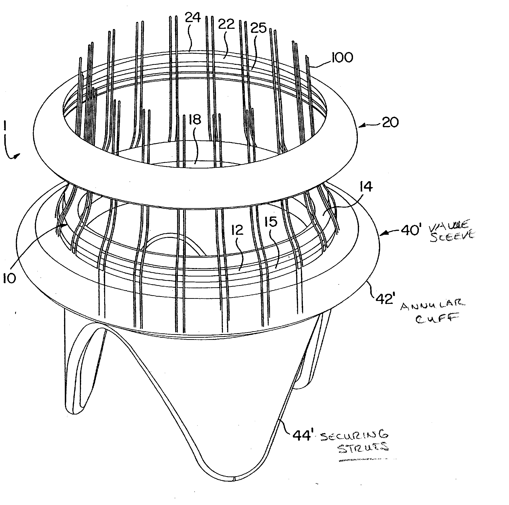
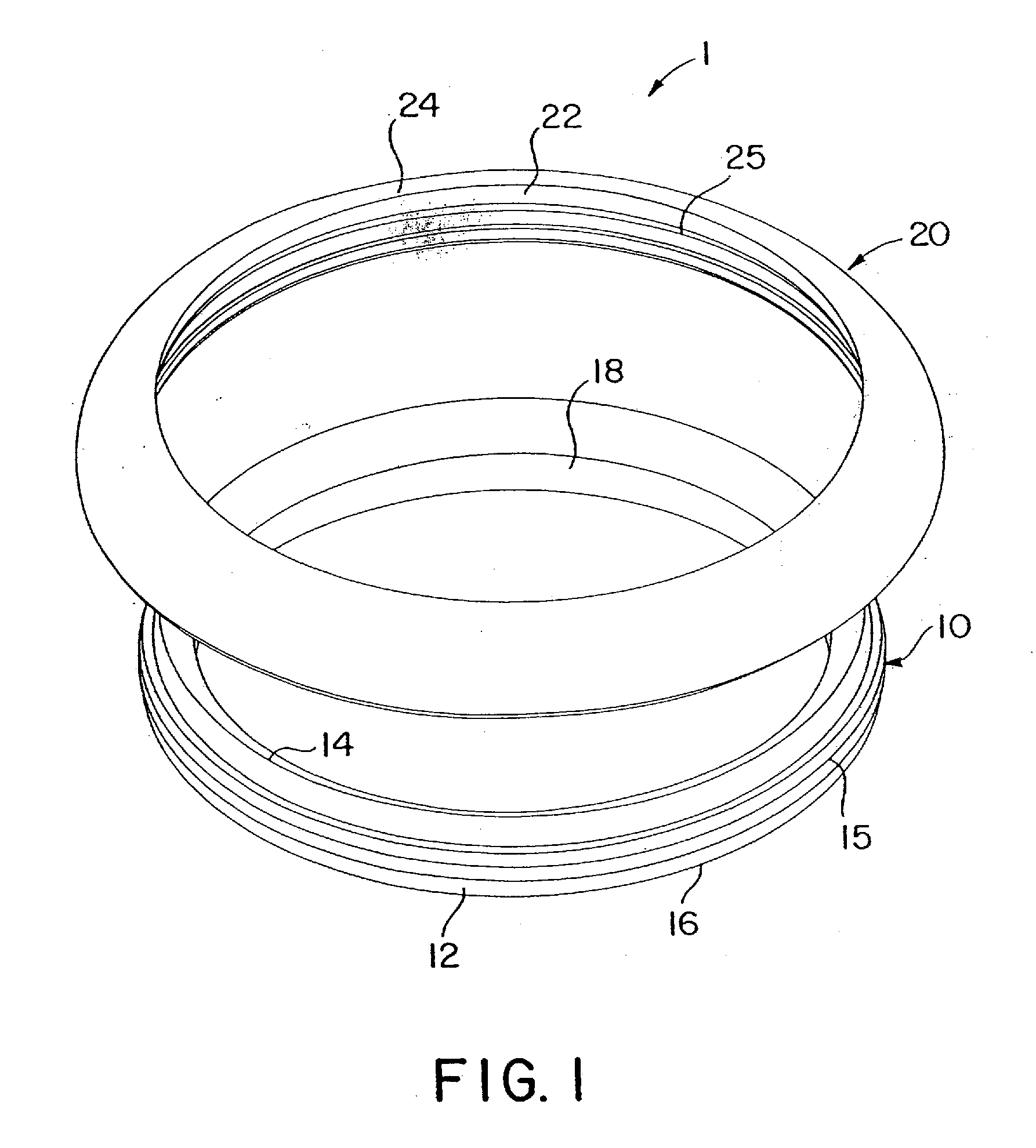
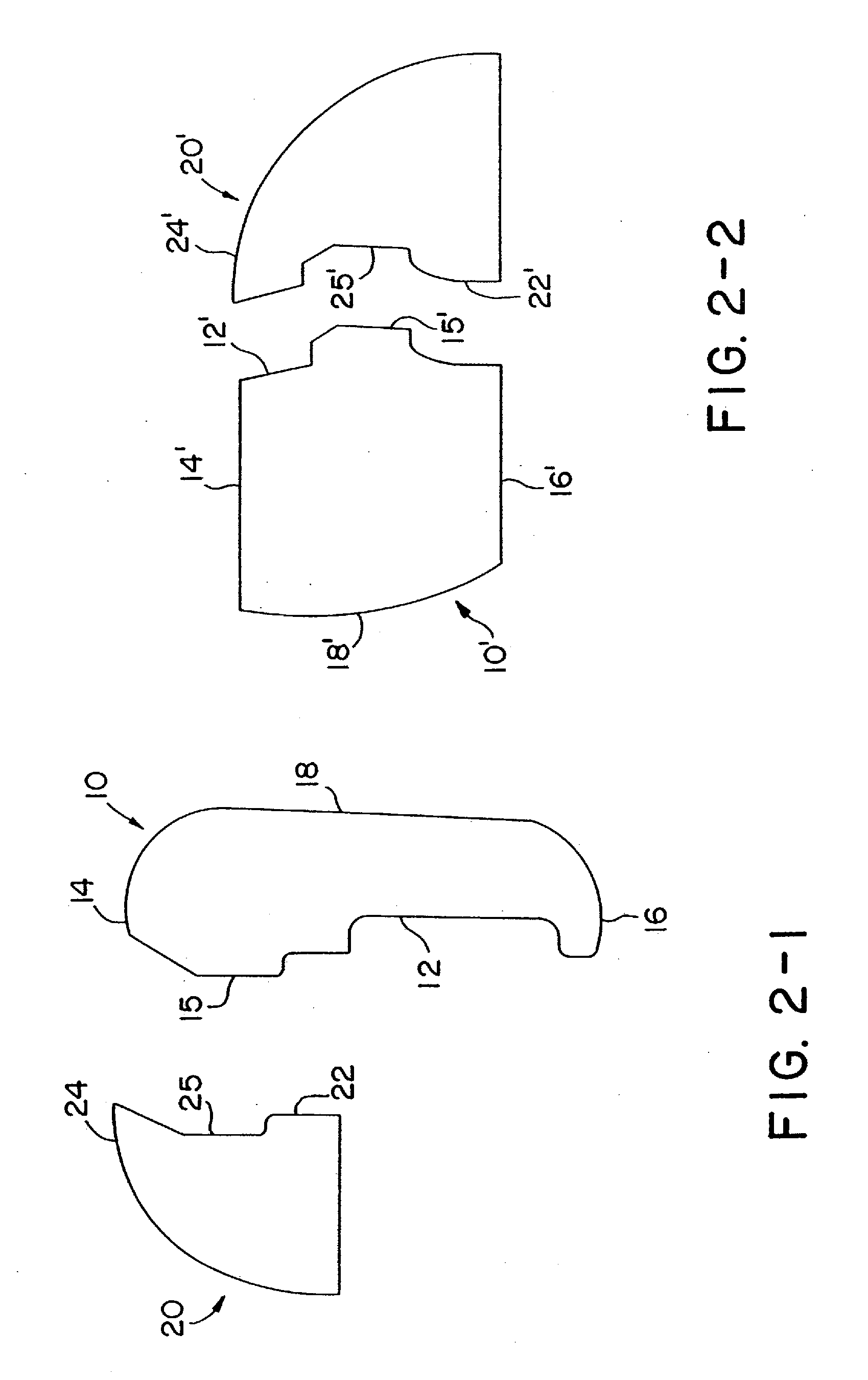
[0033] Referring to FIG. 1, an embodiment of the apparatus 1 is depicted including a first cylinder 10 and a second cylinder 20. The material for cylinders 10 and 20 is chosen to be bio-compatible and anti-thrombogenic. Cylinders 10 and 20 may be made from a suitable metal or plastic, such as Delrin® plastic, manufactured by E.I. DuPont de Nemours and Co. of Wilmington, Del., pyrolitic carbon, or a Titanium-Nickel (95%-5%) alloy. Cylinders 10 and 20 must sufficiently rigid to hold the replacement valve securely during its surgical insertion, but sufficiently flexible to allow second cylinder 20 to be snapped into place over first cylinder 10. Preferably, first cylinder 10 is slightly more rigid than second cylinder 20, so that second cylinder 20 may be snapped into place over first cylinder 10.

[0034] First cylinder 10 comprises an exterior surface 12 and an interior surface 18 and a second (or upper) end 14 and a first (or lower) end 16. Further, first cylinder 10 includes a first ...


PUM


Abstract

A method for automatically fixing sutures to secure a valve sleeve including an annular cuff and a replacement heart valve to an annulus formed in a patient's heart, includes the steps of removing an existing heart valve thereby forming an annulus in the patient's heart, and placing a first cylinder having a first end and a second end and an interior surface and an exterior surface and comprising first securing means formed on the exterior surface adjacent to the second end of the first cylinder, in which the first cylinder includes a valve sleeve having an annular cuff, such that the annular cuff surrounds the exterior surface adjacent to the first end of the first cylinder. The method also includes positioning the annular cuff of the valve sleeve in the annulus and securing the cuff to the annulus with a plurality of sutures, and threading the plurality of sutures over the exterior surface of the first cylinder and over an interior surface of a second cylinder, the second cylinder having second securing means corresponding to and adapted to fixedly engage the first securing means of the first cylinder. Moreover, the method includes creating a blood-tight seal between the cuff of the valve sleeve and the annulus, and securing the plurality of sutures between the first cylinder and the second cylinder by engaging the first securing means of the first cylinder with the second securing means of the second cylinder.

Description

[0001] This application is a divisional application of and claims priority from U.S. patent application Ser. No. 09 / 987,976, which was filed on Nov. 16, 2001, which claims priority from U.S. Provisional Patent Application No. 60 / 248,837, which was filed on Nov. 16, 2000, the disclosures of which are incorporated by reference in their entirety.BACKGROUND OF THE INVENTION [0002] 1. Field of the Invention [0003] The invention relates to apparatus for automatic suture fixation and methods for minimally invasive cardiac surgery employing such apparatus. In particular, the invention relates to apparatus for automatic suture fixation including a first cylinder fitted with first securing means on its exterior surface and a second cylinder with second securing means on its interior surface, whereby sutures may be secured between these cylinders when the corresponding securing means engage. Further, methods for minimally invasive cardiac surgery employing such apparatus may include the steps ...

Claims


Application Information

Patent Timeline
Patent Type & Authority Applications(United States)
IPC IPC(8): A61F2/24A61B17/04
CPCA61B17/0469A61B17/0482A61B2017/0496A61F2/2427
Inventor HILL, J.BRIGGS, GEOFFSIMS, MICHAELHINMAN, CAMERON
Owner HILL J DONALD
Why Eureka
Try Eureka