
Construction module system and method

Inactive Publication Date: 2007-06-14
BAYS RICHARD V
View PDF19 Cites 18 Cited by
  • Summary
  • Abstract
  • Description
  • Claims
  • Application Information

AI Technical Summary

Benefits of technology

[0007] The present invention provides a simplified construction module system and method to form a structure by a minimal crew with little specialized trade skills and minimum equipment in a relatively short time period. Relatively lightweight construction modules can be brought to a construction site and linked together to form the structure. In at least one embodiment the present invention includes foundation modules, wall modules, ceiling modules, and roof modules. Further, the modules can be subdivided into specific modules that can be interchanged with other modules, including a door module, window module, and sub-modules. A designer can simply choose between the various modules depending on the size and layout desired. Other building trades such as finishers, plumbing, and electrical can complete the structure as needed. One or more of the modules can be filled after erection on the jobsite with a filler to add strength or stability to the structure.

Problems solved by technology

Present day construction of a typical building involves extensive time, materials, and attendant costs.
The price is increasing as materials become more expensive, especially wood products.
Trailer housing is less expensive and portable, but is generally not of the quality of the above construction.
The trailer housing can still be relatively expensive.
Thus, those seeking a new structure are generally required to choose between extensive onsite construction that is expensive and time consuming, purchased trailer housing that can still be expensive, and tilt wall construction that requires specialized equipment and trade skills.

Method used


Image

  • Construction module system and method
  • Construction module system and method
  • Construction module system and method

Examples


Embodiment Construction

[0027] In the description that follows, like elements are marked throughout the specifications and drawings with the same reference numerals, respectively. The drawing figures are not to scale. The elements are generally shown in schematic form in the interest of clarity and conciseness.

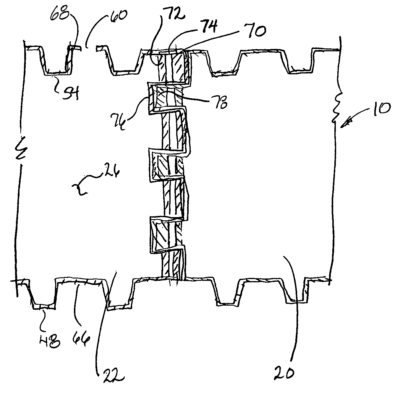
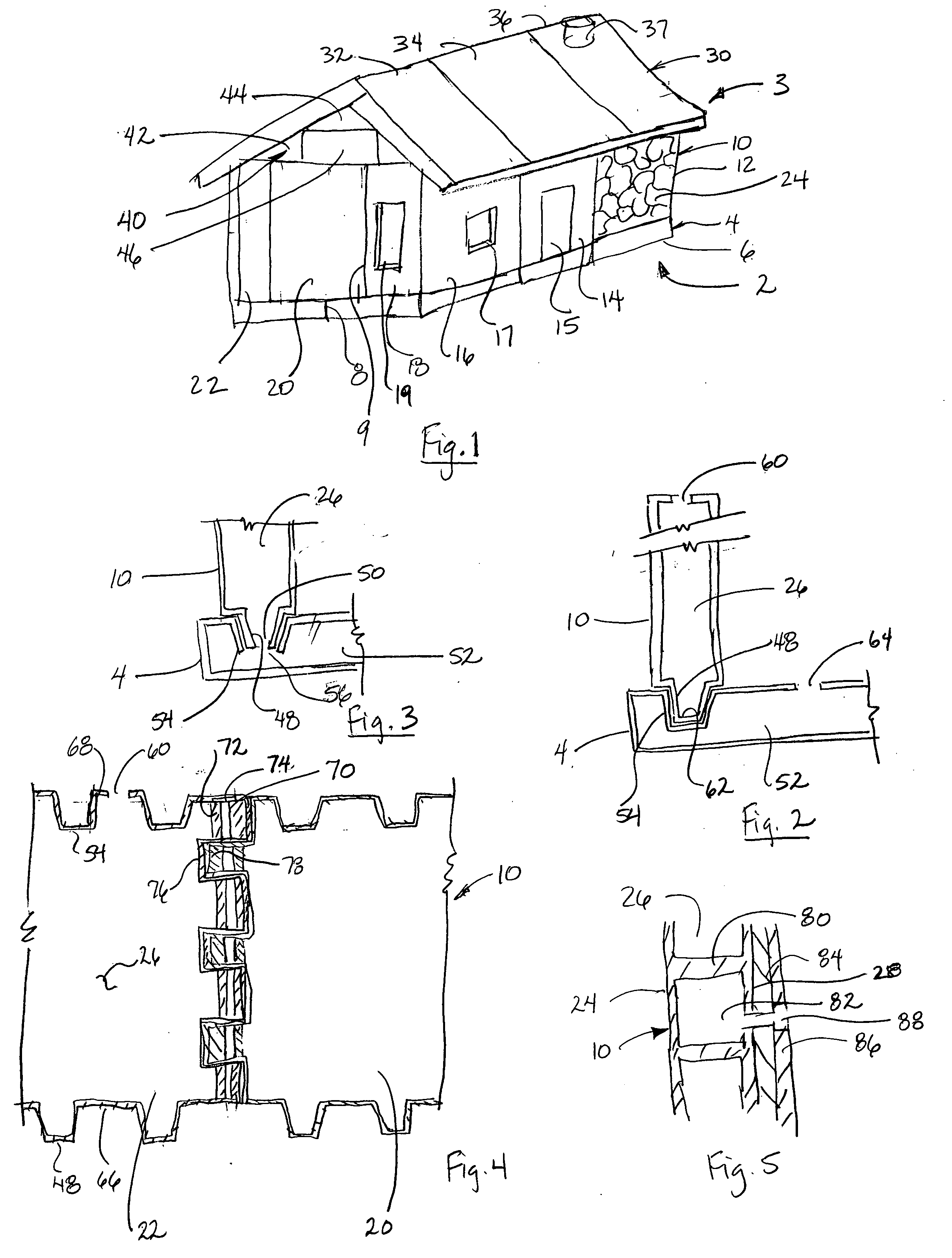
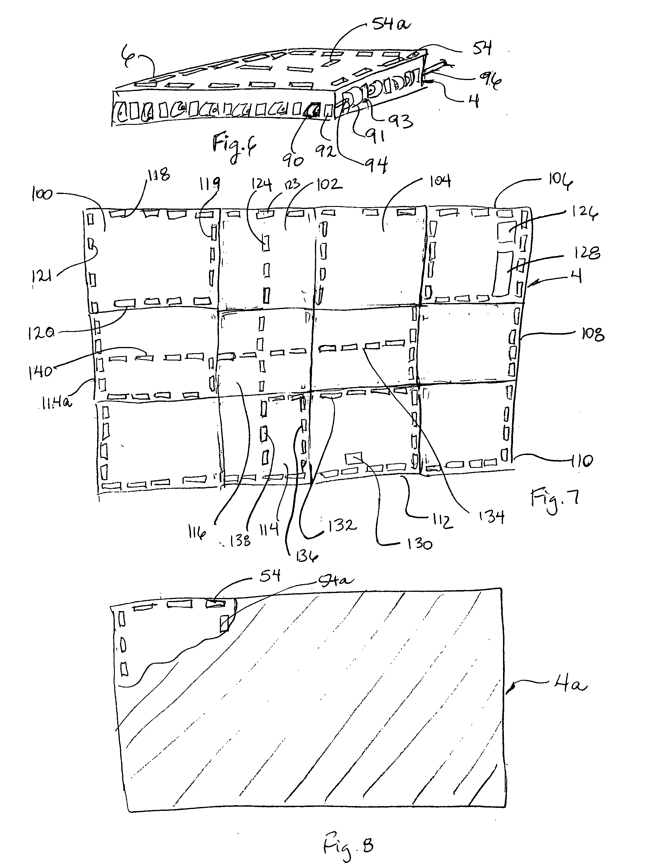
[0028]FIG. 1 is a schematic perspective view of one embodiment of the construction module system. A construction module system 2 generally includes one or more modules that can be coupled together to form a building or other structure 3 of a variety of shapes and sizes. Such structures can include without limitation, residences, garages, storage facilities, buildings, schools, emergency facilities, and so forth. Further, the construction module system can form protective shells over such structures, including mobile homes and other portable structures, that are particularly prone to damage in high winds. In some embodiments, the modules can be removable, for example, after a protective shell is need...


PUM


Abstract

The present invention provides a simplified construction module system and method to form a structure by a minimal crew with little specalized trade skills and minimum equipment in a relatively short time period. Relatively lighweight construction modules can be brought to a construction site and linked together to form the structure. In at least one embodiment the present invention includes foundation modules, wall modules, ceiling modules, and roof modules. Further, the modules can be subdivided into specific modules that can be interchanged with other modules, including a door module, window module, and sub-modules. A designer can simply choose between the various modules depending on the size and layout desired. Other building trades such as finishers, plumbing, and electrical can complete the structure as needed. One or more of the modules can be filled after erection on the jobsite with a filler to add strength or stability to the structure.

Description

FIELD OF THE INVENTION [0001] The present invention relates to the construction industry. More specifically, the present invention relates to modular construction of buildings. BACKGROUND OF THE INVENTION [0002] Present day construction of a typical building involves extensive time, materials, and attendant costs. This known fact is especially true for residential construction. For a typical structure, an area is surveyed and the land prepared to receive the foundation. A foundation crew builds the forms for the foundation, places reinforcement bar or bar screen mesh within the form, coordinates the delivery of the concrete, and smoothes or otherwise finishes the slab. After several days of curing, the frame of the foundation form is removed and the framing crew begins its efforts. The framing crew is responsible for erecting the framing around the house, including the bottom plates, studs, headers, top plates, joists, rafters, soffits, and other structures to the walls, ceiling and...

Claims


Application Information

Patent Timeline
IPC IPC(8): B62D63/04E04B1/34
CPCE04B1/02E04B1/6141E04B1/6179
Inventor BAYS, RICHARD V.
Owner BAYS RICHARD V
Learn More