Power impact tool adapter

Inactive Publication Date: 2007-06-14
MATSUSHITA ELECTRIC WORKS LTD
View PDF7 Cites 25 Cited by
  • Summary
  • Abstract
  • Description
  • Claims
  • Application Information

AI Technical Summary

Benefits of technology

[0010] The power impact tool in accordance with the present invention has a reinforcing connecting portion disposed at a front side of the grip portion. A part of the reinforcing connecting portion is connected to the front end portion of the main body at the back of the clutch handle and to the free end portion of the grip, wherein the reinforcing connecting portion is disposed in front of the grip; and a part protruded most forward among the reinforcing connecting portion is located directly in front of a trigger switch disposed at the base portion of the grip, and a part of the reinforcing connec

Problems solved by technology

However, when employing a heavy battery pack in such a configuration by attaching the battery pack to a bottom of the grip portion in a heavy weight power impact tool as disclosed in Japanese Patent Laid-open Application No. 2002-233673, the rigidity of the housing can be susceptible to a problem unless a reinforcing connecting po

Method used


Image

  • Power impact tool adapter
  • Power impact tool adapter
  • Power impact tool adapter

Examples


Embodiment Construction

[0021] Hereinafter, there will be described embodiments of the present invention with reference to the accompanying drawings.

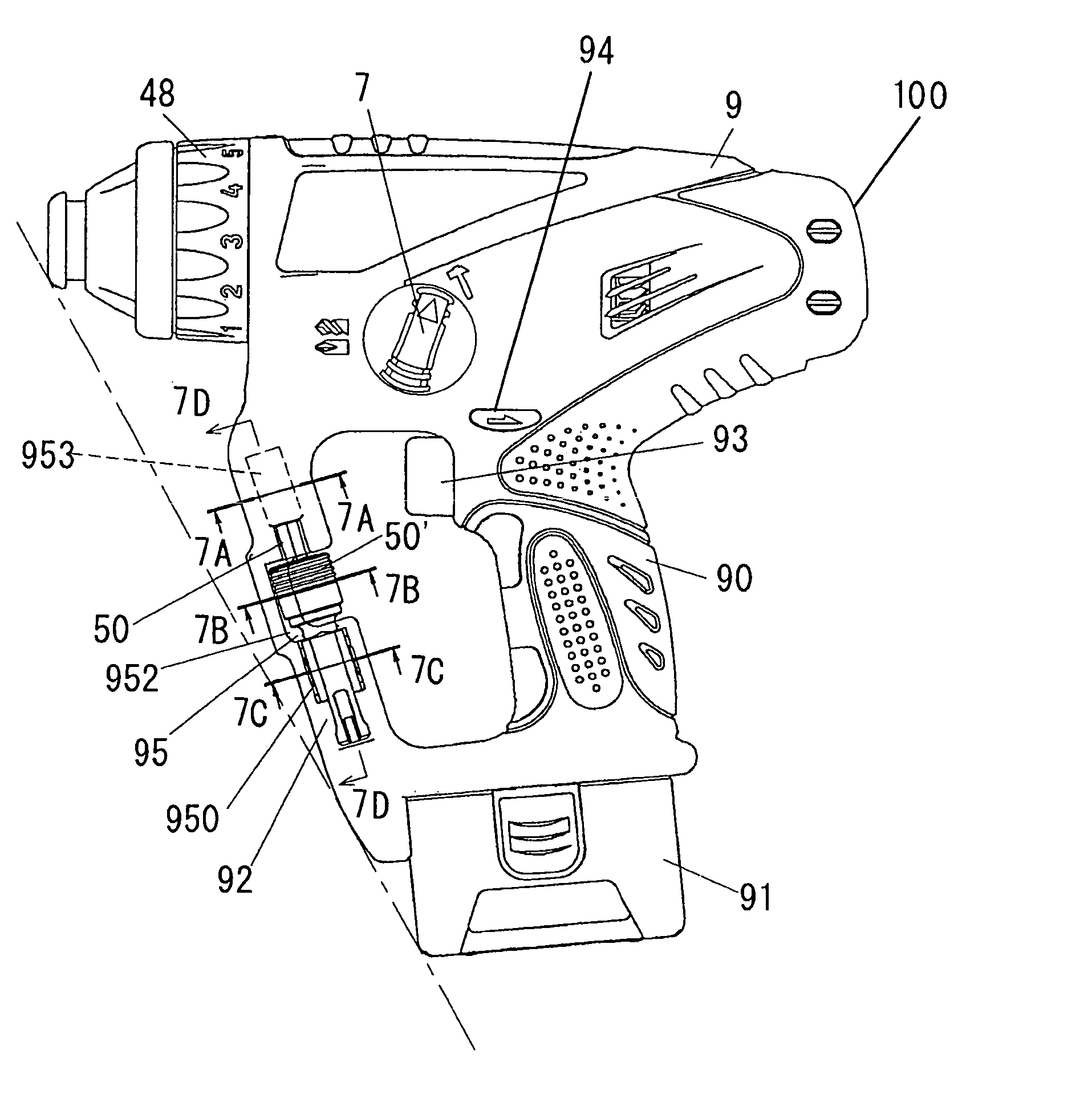
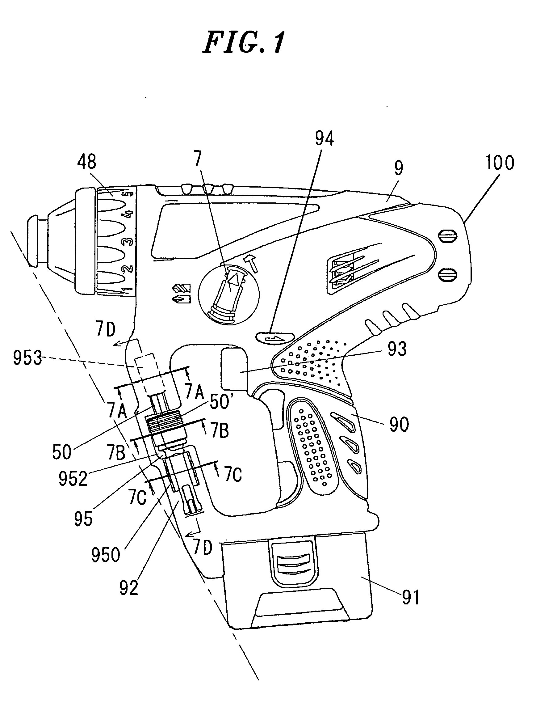
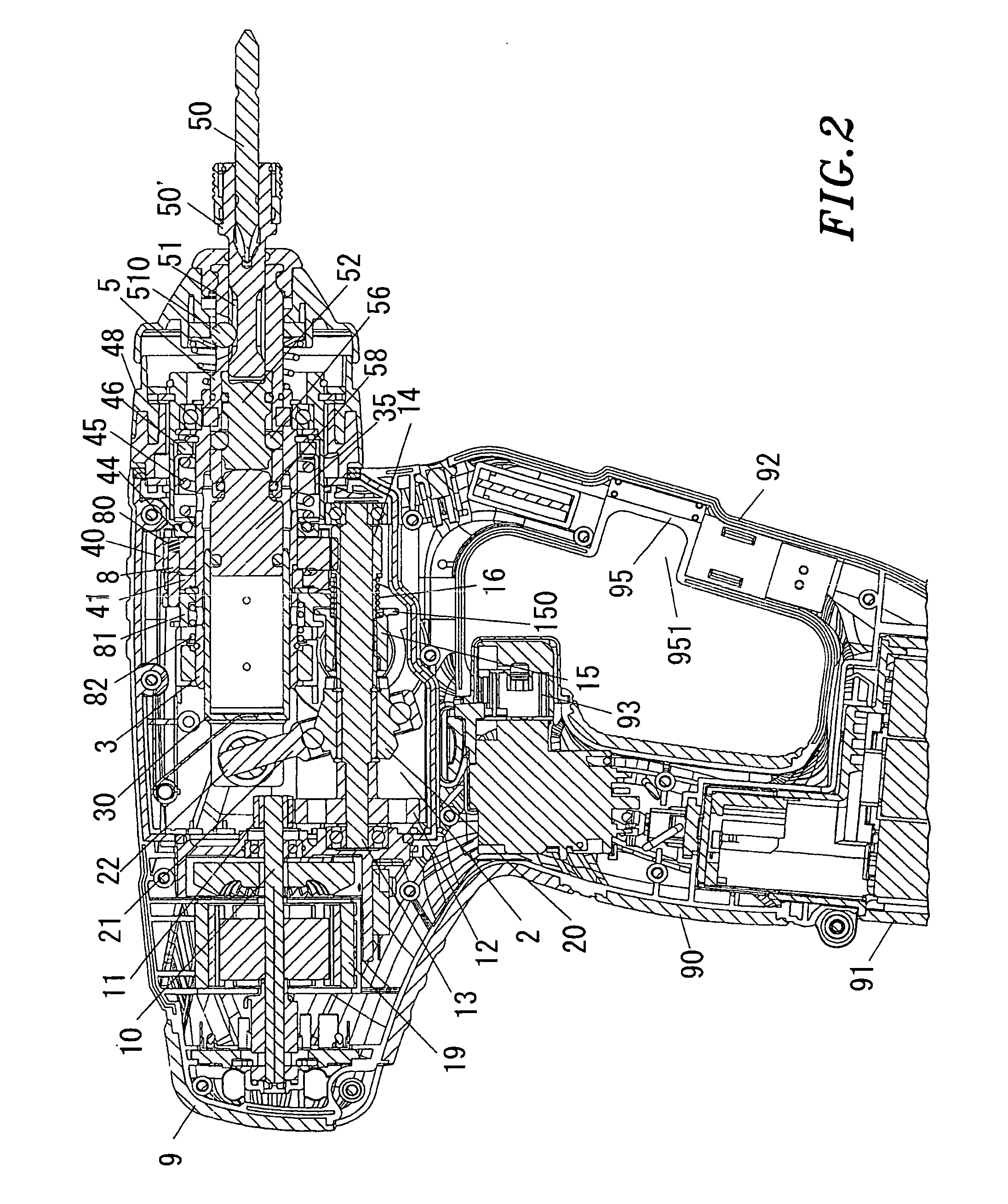
[0022] In an embodiment of the present invention as shown in FIGS. 1 to 9, it is discussed that a power tool shown thereof is a hammer drill capable of transferring a rotational force and applying a striking force in an axial direction and includes a striking-motion-deactivated mode that is capable of transferring only the rotational force to an output bit. Reference numeral 9 in the drawings designates a housing with which a grip portion 90 is formed integrally so as to extend downwardly therefrom. A battery pack 91 is detachably attached to the bottom of the grip portion 90. A housing-reinforcing connecting portion 92 is integrally formed between the bottom frontal end of the grip portion 90 and the front end of the housing 9. Reference numeral 93 in the drawings designates a trigger switch disposed at a base portion of the grip portion 90. Disposed within ...


PUM


Abstract

A power impact tool includes a main body accommodating a chuck at a front end portion thereof; a clutch handle for setting a torque applied to the chuck; a grip including a base portion; a free end portion; and a reinforcing connecting portion connected to the front end portion of the main body at the back of the clutch handle and to the free end portion of the grip. The reinforcing connecting portion is disposed in front of the grip; and a part protruded most forward among the reinforcing connecting portion is located directly in front of the trigger switch disposed at the base portion of the grip. A part of the reinforcing connecting portion disposed behind the clutch handle retreats backward toward the free end portion of the grip.

Description

FIELD OF THE INVENTION [0001] The present invention relates to a power impact tool; and, more particularly, to a power impact tool having a striking-motion-activated mode for transferring a rotational force and applying a striking force in an axial direction and a striking-motion-deactivated mode for transferring only the rotational force. BACKGROUND OF THE INVENTION [0002] As for a power impact tool which is capable of transferring a rotational force and applying a striking force in an axial direction to an output bit, there has been provided a hammer drill for use in a concrete boring operation and the like. When such a hammer drill is provided with a striking-motion-deactivated mode as an addition, the same hammer drill can be used to create a hole on a concrete (the concrete boring operation) as well as to fasten a screw to an anchor inserted into the hole (a screw fastening operation), wherein the striking-motion-deactivated mode is configured to transfer only the rotational fo...

Claims


Application Information

Patent Timeline
IPC IPC(8): E02D7/02
CPCB23B31/005B23B2231/0264B23B2231/0276B25D16/003B25D16/006B25D17/04B25D2211/061B25D2216/0023B25D2216/0038B25D2250/165B25F5/02B25F5/029
Inventor HASHIMOTO, KOICHITSUBAKIMOTO, HIROYUKITATSU, KUNIHIKO
Owner MATSUSHITA ELECTRIC WORKS LTD
Why Eureka
Try Eureka