Switching device

a technology of switching device and switch body, which is applied in the direction of emergency protective device, switch power arrangement, snap-action arrangement, etc., can solve the problems of complex assembly and achieve the effect of simple structur

Active Publication Date: 2007-06-14
ABB (SCHWEIZ) AG
View PDF8 Cites 38 Cited by
  • Summary
  • Abstract
  • Description
  • Claims
  • Application Information

AI Technical Summary

Benefits of technology

[0008] An advantage of the switching devi

Problems solved by technology

The problem in known switching devices is to accomplish the testing position.
In some known switching devic

Method used


Image

  • Switching device
  • Switching device
  • Switching device

Examples


Embodiment Construction

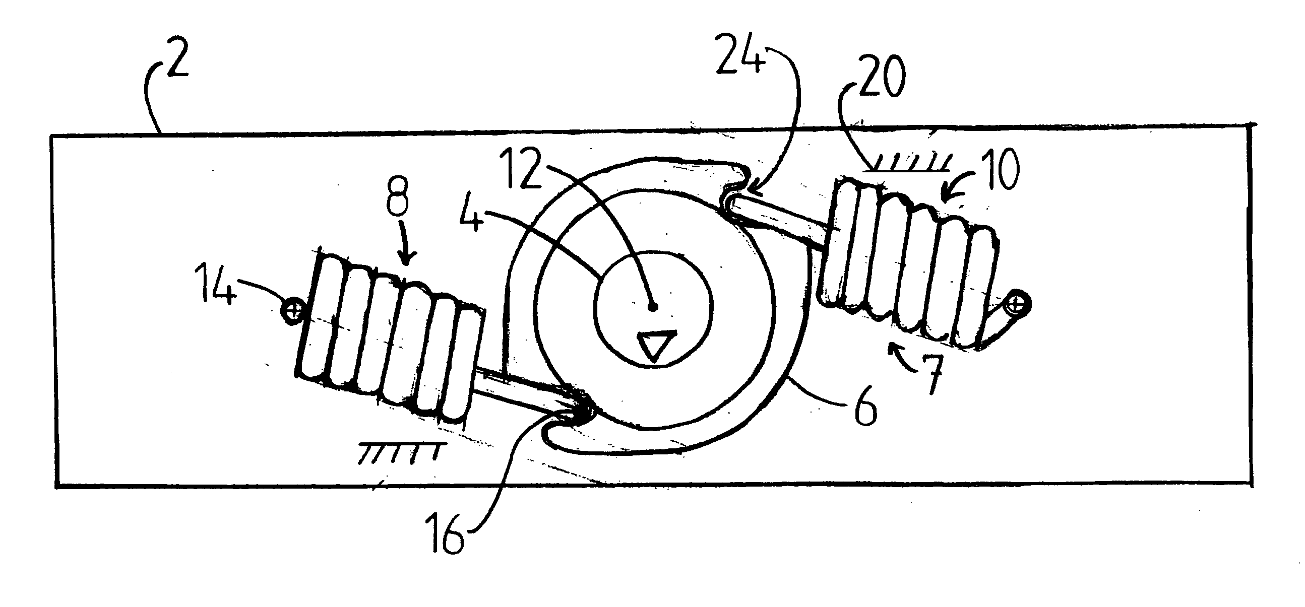
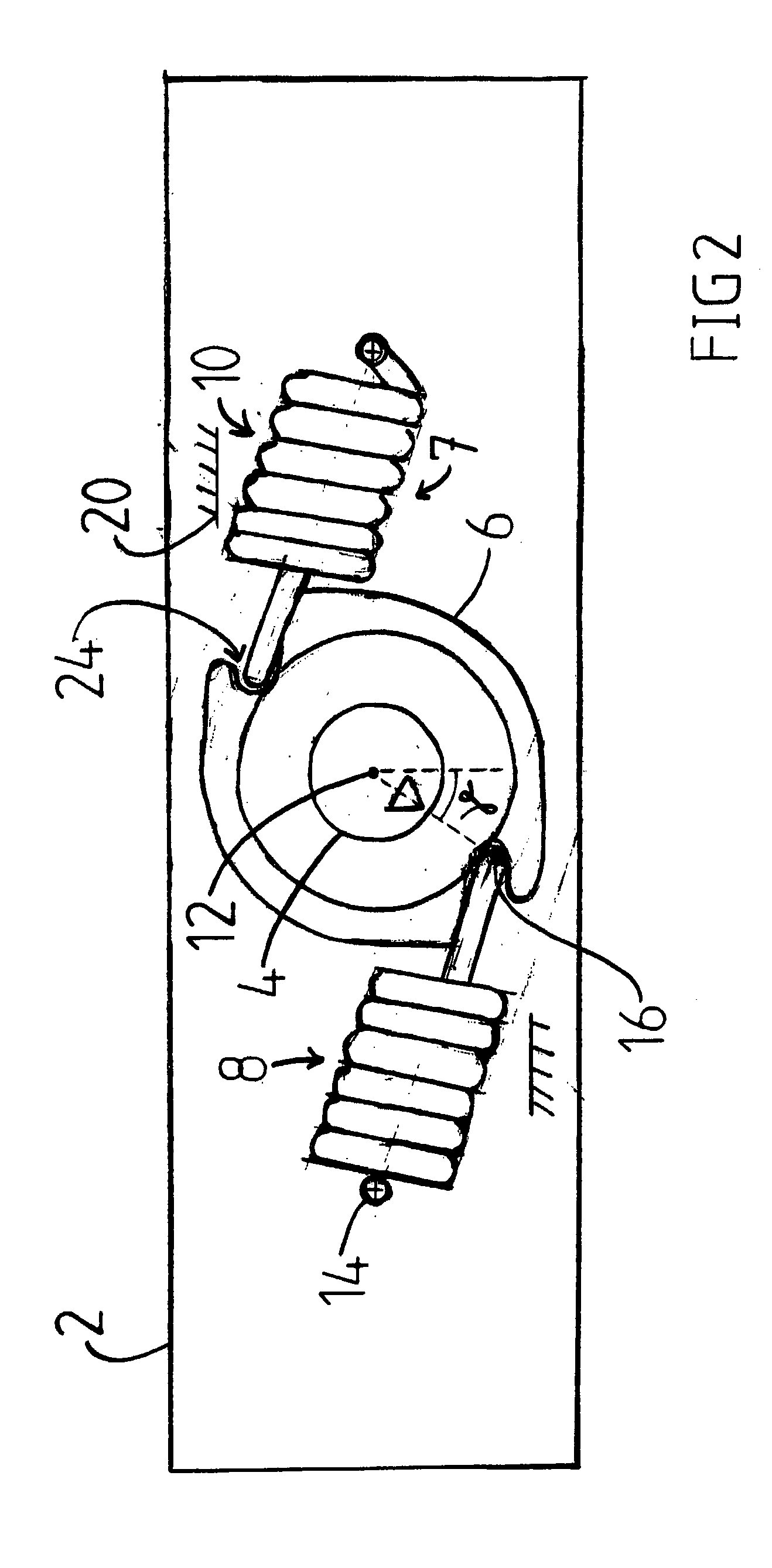
[0016] FIGS. 1 to 4 show the operating mechanism of a switching device according to an embodiment of the invention. The operating mechanism comprises a control shaft 4, an actuator 6, and spring means 7 assembled in a frame 2.

[0017] The actuator 6 is rotatable around an axis 12 of rotation and arranged to rotate the main shaft of the switching device. The control shaft 4 is rotatable around the axis 12 of rotation and adapted to rotate the actuator 6. The control shaft 4 is connected to the actuator 6 by connecting means comprising a spiral spring means 28. An example of the implementation of the connecting means is shown in FIG. 6, which will be dealt with later. The spring means 7 comprise two working springs 8 and 10, each having a first end 14 supported rotatable to the frame 2, and a second end 16. The first end 14 of each working spring is thus hinged to the frame 2 in a manner allowing the second end 16 of the working spring to move circumferentially relative to the first en...


PUM


Abstract

A switching device having a frame, in which an actuator adapted to rotate a main shaft of the switching device and rotatable around an axis of rotation, the actuator having a 0 position, an I position and a first dead point between the 0 position and the I position, the I position being located by a given angle (α6) in a first direction relative to the 0 position. The actuator also has a testing position, the testing position being located by a predetermined angle (β6) in a second direction relative to the 0 position, the second direction being opposite relative to the first direction.

Description

BACKGROUND OF THE INVENTION [0001] The invention relates to a switching device according to the preamble of the independent claim. [0002] Switching devices are instruments employed for opening and closing an electric circuit. The switching device comprises at least one pole and a control device adapted to open and close said pole. Switching devices include switches and switch-fuses, for example. [0003] Switching devices have a 0 position, wherein the poles of the switching device are open, and an I position, wherein the poles of the switching device are closed. The positions of the poles of the switching device are changed by rotating the main shaft of the switching device. For rotating the main shaft, switching devices are provided with an actuator having a 0 position and an I position, which correspond to the 0 position and I position of the switching device. [0004] Some switching devices also have a testing position, wherein the poles of the switching device are open, but the pos...

Claims


Application Information

Patent Timeline
IPC IPC(8): H02B11/00H01HH01H3/22H01H3/32H01H19/20H01H19/22H01H19/24
CPCH01H19/22H01H19/24H01H2300/052
Inventor MATTLAR, HARRISUUTARINEN, AKIKOLMONEN, RAINER
Owner ABB (SCHWEIZ) AG
Why Eureka
Try Eureka