Multi-sample microfluidic dielectrophoresis separating device and method thereof

a microfluidic dielectrophoresis and separating device technology, applied in the direction of fluid pressure measurement, liquid/fluent solid measurement, peptide measurement, etc., can solve the problems of short collection device, difficult screening purity, and inability to mass-screen at one tim

Inactive Publication Date: 2007-06-14
IND TECH RES INST
View PDF1 Cites 34 Cited by
  • Summary
  • Abstract
  • Description
  • Claims
  • Application Information

AI Technical Summary

Benefits of technology

[0009] The foregoing and other features and advantages of the present invention will be more

Problems solved by technology

However, the screening speed depends on the speed while detecting each respective cell by the laser and the voltage switching speed, making the mass screening at one time impossible.
Whereas, the control over different cell collection

Method used


Image

  • Multi-sample microfluidic dielectrophoresis separating device and method thereof
  • Multi-sample microfluidic dielectrophoresis separating device and method thereof
  • Multi-sample microfluidic dielectrophoresis separating device and method thereof

Examples


Embodiment Construction

[0017] The present invention will now be described more specifically with reference to the following embodiments. It is to be noted that the following descriptions of preferred embodiments of this invention are presented herein for the purposes of illustration and description only; it is not intended to be exhaustive or to be limited to the precise form disclosed.

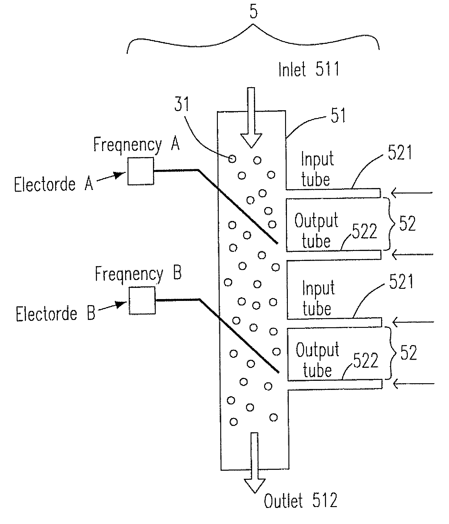
[0018] Please refer to FIG. 5, which is a schematic view showing a multi-sample microfluidic dielectrophoresis separating device according to a preferred embodiment of the present invention. The working principle of the multi-sample microfluidic dielectrophoresis separating device 5 is illustrated with reference to FIG. 5. The device 5 is composed of a primary passage 51 and two secondary passages 52 (the number of the secondary passage can be plural and is not limited to two as illustrated in this embodiment), and the secondary passage 52 includes an input path 521 and an output path 522 and the primary passage 51 include...


PUM

PropertyMeasurementUnit
Forceaaaaaaaaaa
Flow rateaaaaaaaaaa
Speedaaaaaaaaaa

Abstract

A microfluidic dielecttrophoresis separating device is provided. The microfluidic dielectrophoresis separating device includes a primary passage, at least a secondary passage and at least an electrode assembly. The primary passage has a primary flow containing a plurality of particulates flowing therein. The secondary passage has an input path and an output path and is connected with the primary passage. The electrode assembly generates a dielectrophoresis force to drive a specific one of the particulates into the output path.

Description

FIELD OF THE INVENTION [0001] The present invention relates to a multi-sample microfluidic dielectrophoresis separating device, in particular to a multi-sample microfluidic dielectrophoresis separating device combining the technologies from both of the dielectrophoresis (DEP) field and the microfluidic field. BACKGROUND OF THE INVENTION [0002] Please refer to FIG. 1, which is a schematic view showing a conventional micro flow cytometer. The device diminishes the conventional flow cytometer 1, utilizes the electrokinetic-focusing and the collection via the switch channels 11 at the tail end and employs a buried optical fiber and laser to detect the type of the cell 12. The desired cells 12 are distributed to one of the switch channels at the tail end by the electrokinetic method. The advantage is that the purity of the collection is better. However, the screening speed depends on the speed while detecting each respective cell by the laser and the voltage switching speed, making the m...

Claims


Application Information

Patent Timeline
IPC IPC(8): B03C5/02B01D57/02
CPCB01L3/50273B01L3/502761B01L2200/0647B01L2300/0864B01L2400/0424B03C5/026
Inventor YU, TUNG-MINGLIU, CHENG-HSIANG
Owner IND TECH RES INST
Why Eureka
Try Eureka