
Pop-Up Rubber Band Dispenser

Inactive Publication Date: 2007-06-14
COTSALAS STEPHEN
View PDF10 Cites 4 Cited by
  • Summary
  • Abstract
  • Description
  • Claims
  • Application Information

AI Technical Summary

Benefits of technology

[0012] To obtain a rubber band, a user reaches into the upper container and grasps part of a rubber band that is either partially projecting through the aperture or is accessible through the aperture. Upon pulling the one rubber band from the dispenser, due to the compression of the rubber bands and the resulting increased friction between each rubber band, the one rubber band pulls other rubber bands at least partially through the aperture. This results in a plurality of rubber bands extending at least partially through the aperture, whereby such rubber bands may be easily selected and grasped when subsequently desired. Several rubber bands may, in fact, be caused to completely traverse the aperture, as illustrated in FIGS. 6 and 7. Such rubber bands are thereby held in the upper container where they may be, in turn, easily selected and grasped when another rubber band, perhaps of a particular size or color, is desired.
[0014] The present invention is a rubber band dispenser that provides easy one-handed access to rubber bands contained therein. The present invention can be configured to hold a large number of rubber bands in a fairly small desktop footprint. Further, the present device urges subsequent rubber bands to “pop-up” ready for dispensing upon pulling out a first rubber band. The present invention can be easily adapted to not lift up from the desk or table top when a rubber band is pulled therefrom, and can be made relatively inexpensively and efficiently by injection molding techniques. Further, the present invention is easy to refill quickly with rubber bands, and allows for the user to select a particular color or size of rubber band, if desired. The present device if flexible in that it can be manufactured as a permanent refillable device, or marketed as a disposable device pre-filled with rubber bands. Other features and advantages of the present invention will become apparent from the following more detailed description, taken in conjunction with the accompanying drawings, which illustrate, by way of example, the principles of the invention.

Problems solved by technology

Consumable office products, such as paper clips and rubber bands, tend to collect in drawers or desktop trays in a somewhat unorganized manner.
Rubber bands, however, due to their elasticity, are sometimes difficult to manage.
Pulling one rubber band out of a container, such as a simple tray, for example, often results in several other rubber bands spilling out over the side.
Further, if the tray is inadvertently tipped or inverted, rubber bands can spill out of the tray easily.
While such a device has the advantage that tipping it over will not result in a massive spill of rubber bands, such rubber band balls do have several drawbacks, one of which is that they are difficult to use with one hand, such as is often desired, particularly if one's other hand is holding a phone or the like.
Another drawback is that at a certain point, when the rubber bands are depleted in such a rubber band ball, the rubber bands will just fall apart in a heap and will need to be stored in a container or bag of some sort anyway.
Yet another drawback is that you can only pick-out the top-most rubber band.
In the case where the user is desiring a rubber band of a particular color or size, it may be trapped by undesired outermost rubber bands.
Further, such a device needs to be carefully loaded with rubber bands before use, which is time consuming and inconvenient.
While such a device is more effective than the previously mentioned prior art solutions, this type of device has several drawbacks as well.
Principally, when fully loaded, rubber bands often are pulled out together due to friction between rubber bands.
Further, such a device makes no provision for securing the device to the table or desk, which results in the device being lifted from the desk when attempting to pull a rubber band from the device and the device is fairly full of rubber bands.
Further, the footprint of such a device is fairly large compared to its height, and thus it takes up a fair amount of space on the desktop for the number of rubber bands it can hold.

Method used


Image

  • Pop-Up Rubber Band Dispenser
  • Pop-Up Rubber Band Dispenser
  • Pop-Up Rubber Band Dispenser

Examples


Embodiment Construction

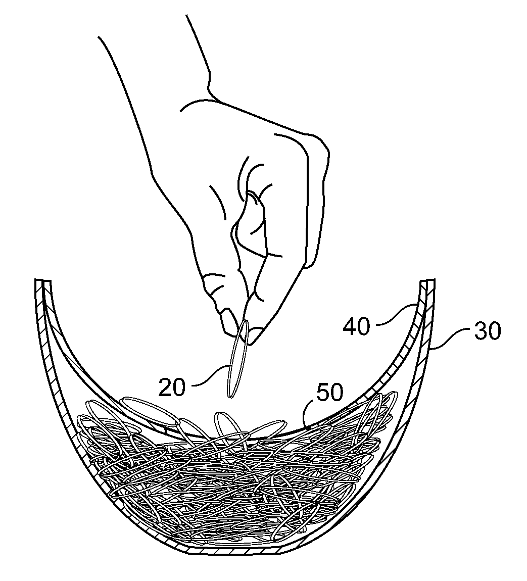
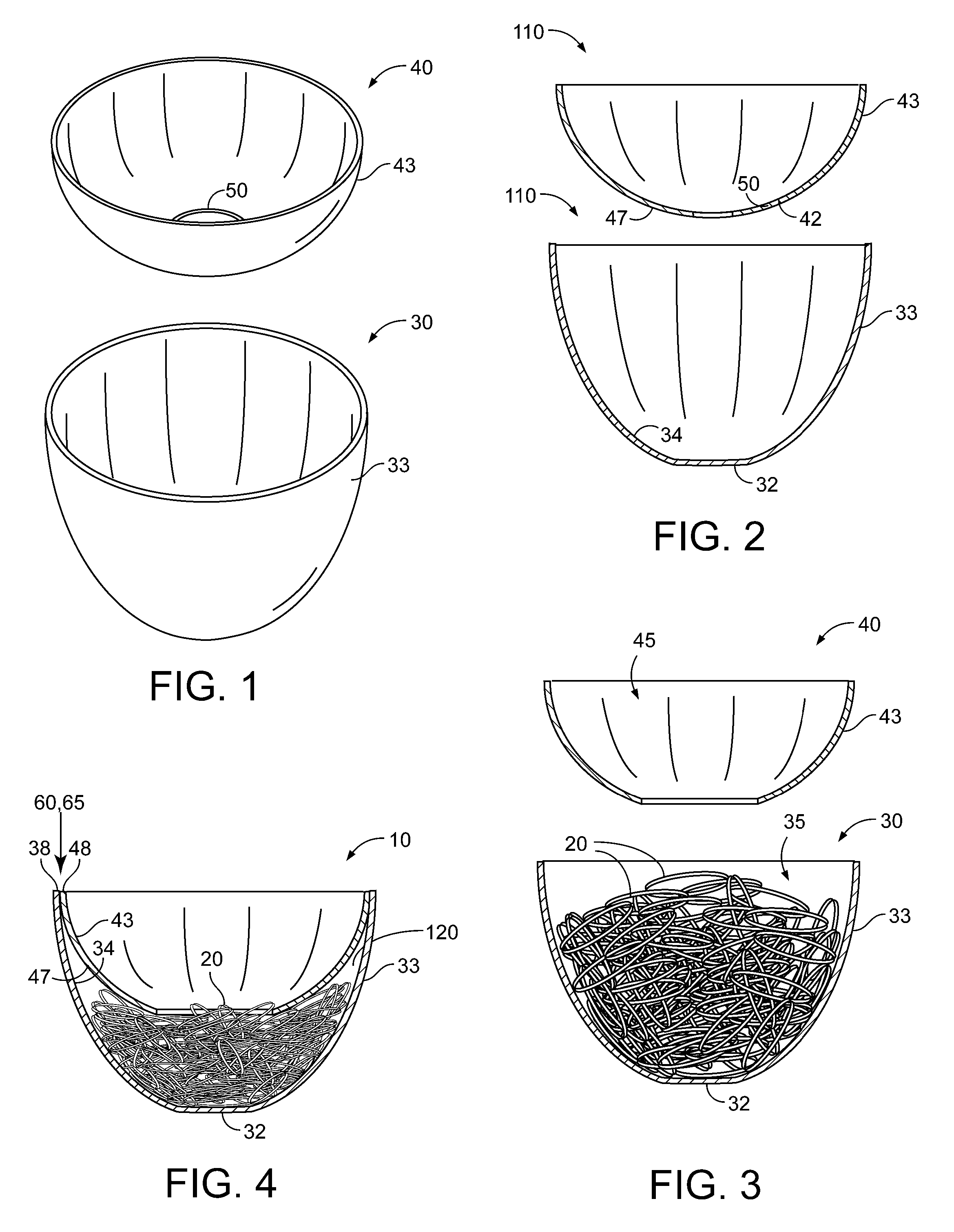
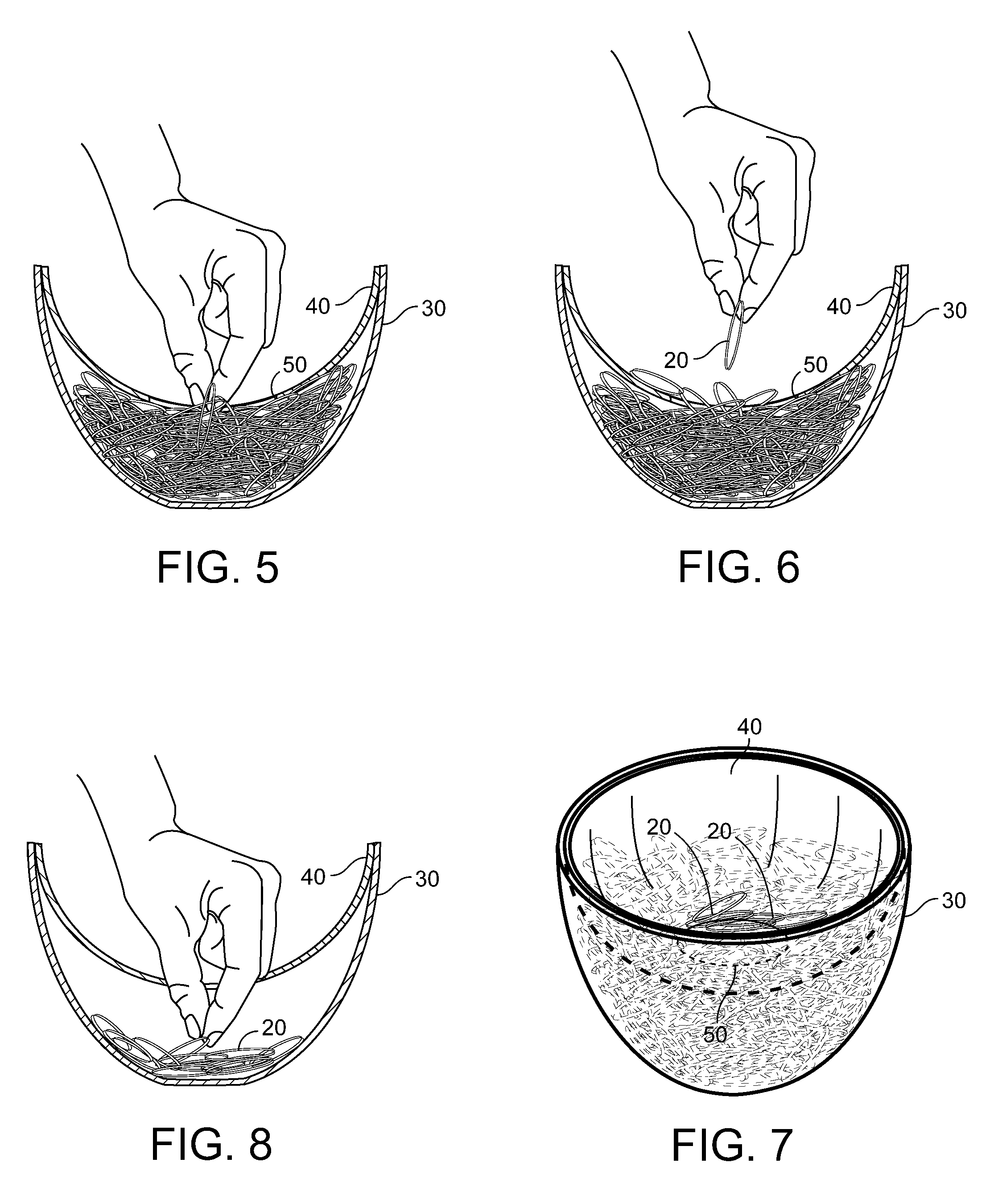
[0027]FIGS. 1 & 4 illustrate a dispenser 10 for dispensing rubber bands 20. The dispenser 10 comprises, in its most general form, a lower container 30 and an upper container 40. The lower container 30 is open at a top end 35 thereof and comprises at least one side wall 33 and one bottom wall 32 (FIGS. 1-3). The bottom wall 32 has an upward facing inner surface 34.

[0028] The upper container 40 is likewise open at a top end 45 thereof, and comprises at least one side wall 43 and one bottom wall 42. The bottom wall 42 includes an aperture 50 therein (FIGS. 1 and 2) and a downward-facing outer surface 47 (FIG. 2).

[0029] Each container 30,40 is preferably made from an at least semi-rigid plastic material, but can also be fashioned from metal, wood, or any other suitably rigid or semi-rigid material. Further, each container 30,40 may be made from a translucent or transparent material, whereby the amount of rubber bands 20 contained therein may be easily observed. Each container 30,40 ma...


PUM

PropertyMeasurementUnit
Forceaaaaaaaaaa
Volumeaaaaaaaaaa
Shapeaaaaaaaaaa

Abstract

A dispenser for dispensing rubber bands is disclosed, the dispenser comprising a lower container and an upper container. The lower container is open at a top end thereof and comprises at least one side wall and one bottom wall. The bottom wall has an upward facing inner surface. The upper container is likewise open at a top end thereof, and comprises at least one side wall and one bottom wall. The bottom wall includes an aperture therein and a downward-facing outer surface. The lower container encompasses a larger volume than the upper container, the difference between the volume of the two containers being essentially the storage volume for rubber bands. In use, the lower container is filled with rubber bands. The upper container is then pressed down such that the upper container nests within the lower container, thereby compressing the plurality of rubber bands between the outer surface of the upper container and the inner surface of the lower container. To obtain a rubber band, a user reaches into the upper container and grasps part of a rubber band that is either partially projecting through the aperture or is accessible through the aperture. Upon pulling the one rubber band from the dispenser, due to the compression of the rubber bands and the resulting increased friction between each rubber band, the one rubber band pulls other rubber bands at least partially through the aperture. This results in a plurality of rubber bands extending at least partially through the aperture, whereby such rubber bands may be easily selected and grasped when subsequently desired.

Description

CROSS-REFERENCE TO RELATED APPLICATIONS [0001] The application claims the benefit of Provisional Patent Application 60 / 748,454, filed on Dec. 08, 2005.STATEMENT REGARDING FEDERALLY SPONSORED RESEARCH AND DEVELOPMENT [0002] Not Applicable. FIELD OF THE INVENTION [0003] This invention relates to office products and, more specifically, to an improved rubber band dispenser. DISCUSSION OF RELATED ART [0004] Consumable office products, such as paper clips and rubber bands, tend to collect in drawers or desktop trays in a somewhat unorganized manner. To keep such items organized, it is well known to contain such products in a container of some fashion. Rubber bands, however, due to their elasticity, are sometimes difficult to manage. Pulling one rubber band out of a container, such as a simple tray, for example, often results in several other rubber bands spilling out over the side. Further, if the tray is inadvertently tipped or inverted, rubber bands can spill out of the tray easily. [00...

Claims


Application Information

Patent Timeline
IPC IPC(8): B65D71/00
CPCA47F1/06B65D83/0805B65D83/0817
Inventor COTSALAS, STEPHAN
Owner COTSALAS STEPHEN
Learn More