Smartcard and magnetic stripe emulator with biometric authentication

a biometric authentication and smartcard technology, applied in the field of smartcard and magnetic stripe emulators with biometric authentication, can solve the problems of unauthorized purchases, fraudulent and illegal trends, and small improvement in security to protect account data, so as to prevent both unauthorized use of the device and outright theft. , the effect of cost effectiv

Inactive Publication Date: 2007-06-14
X CARD HLDG
View PDF43 Cites 348 Cited by
  • Summary
  • Abstract
  • Description
  • Claims
  • Application Information

AI Technical Summary

Benefits of technology

[0008] The present invention is a cost effective device capable of storing the information from multiple smartcards and data from multiple conventional magnetic stripe cards for use either through a magnetic stripe emulator or as a ‘virtual’ contactless smartcard, and preventing both unauthorized use of the device and outright theft of the information on the device via a biometric recognition technology, such as, for example, fingerprint verification or voice recognition. In this capacity, the theft of account data via relay attack, as well as crimes associated with lost or stolen smartcards, will be virtually eliminated.

Problems solved by technology

While smart cards allow transactions to be performed at a faster rate than traditional magnetic stripe cards, they only offer a small improvement in security to guard against account data theft than the conventional magnetic stripe credit cards they are replacing.
A closer examination of this technology reveals several inadequacies that will allow fraudulent and illegal trends to emerge.
First, owners making a purchase no longer enter PIN numbers or sign a printed copy of the credit card transaction.
Therefore, if a smartcard is lost or stolen, it can be used to make unauthorized purchases.
Also, there are new security threats that are technically possible against contactless smart cards.
These deficiencies represent a dramatic financial threat to both the issuing institutions and the card owners.
While credit card companies and insurance companies that underwrite fraud coverage usually absorb the losses associated with fraudulent activity, the long-term implications for victims and their credit ratings are very serious.
Additionally, it is intuitive that any perceived security risk associated with smartcard technology would represent an obstacle to widespread market acceptance.

Method used


Image

  • Smartcard and magnetic stripe emulator with biometric authentication
  • Smartcard and magnetic stripe emulator with biometric authentication
  • Smartcard and magnetic stripe emulator with biometric authentication

Examples


Embodiment Construction

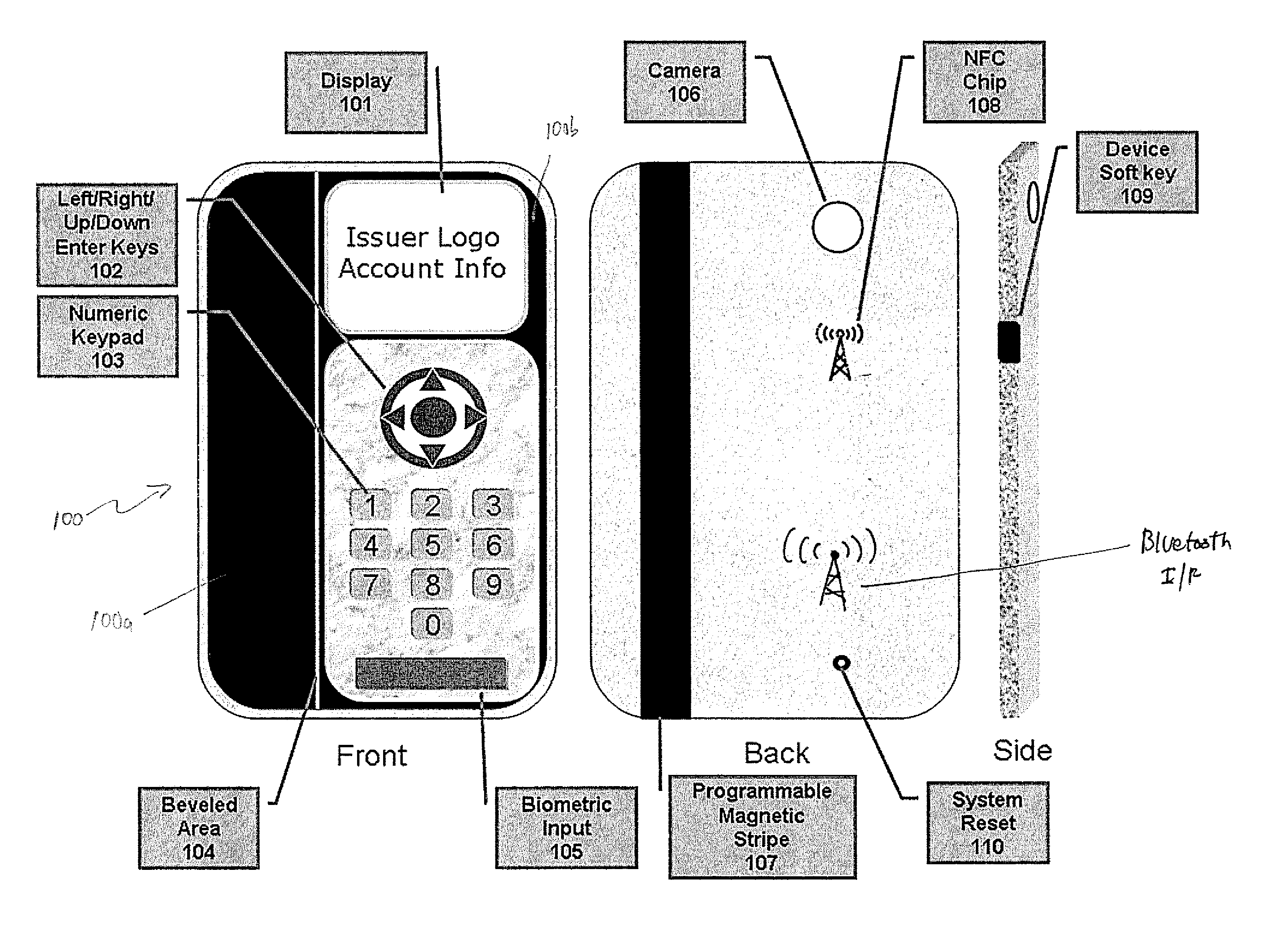
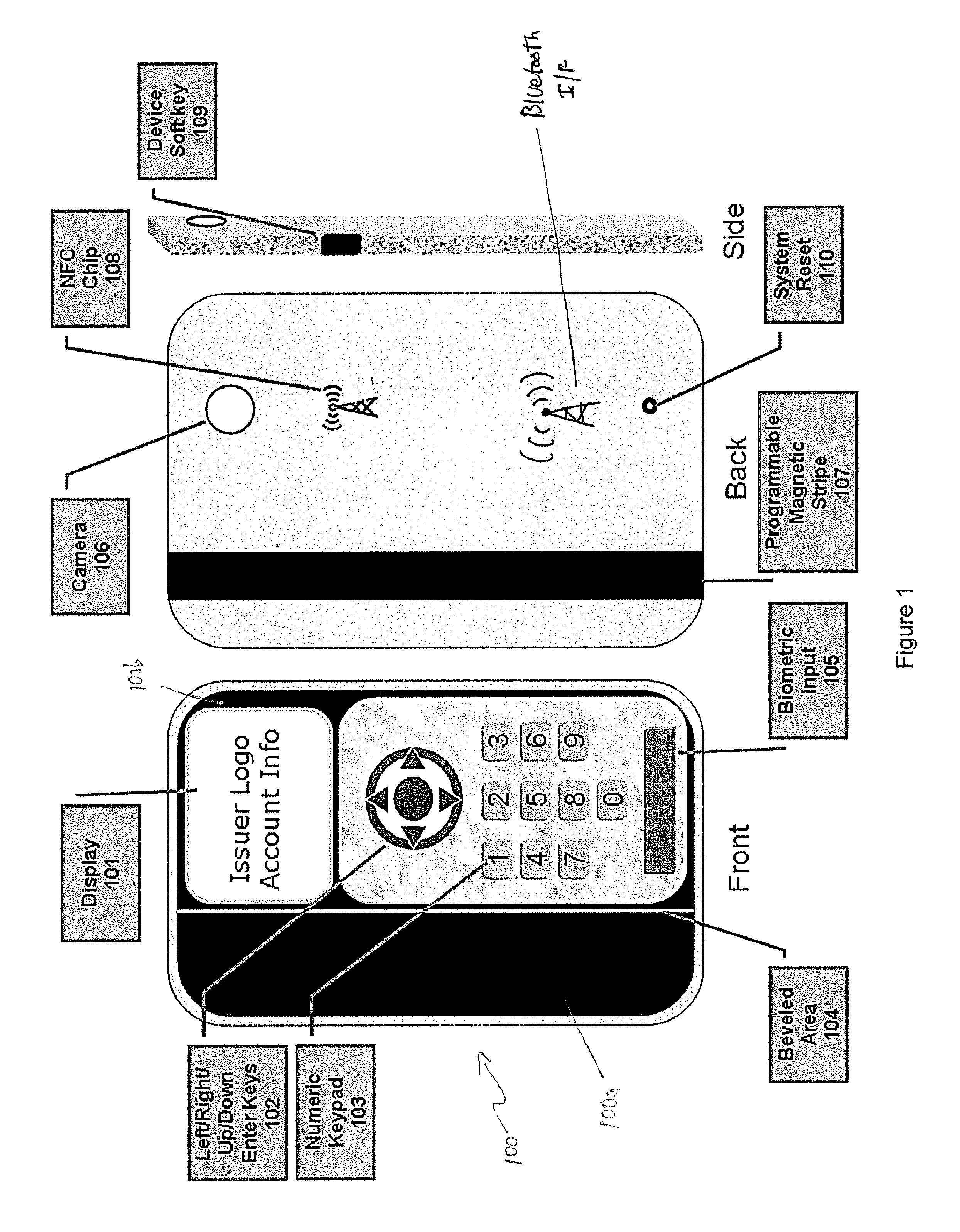
[0034]FIG. 1 shows front, back and side views of the exterior of the device, which contains two portions, thinner portion 100a and thicker portion 100b. Thicker portion 100b preferably is about 10 mm thick and may be composed of any material commonly used for housing electronic devices, but is preferably composed of a material that will not interfere with the transmission or reception of RF signals. The front of device 100 contains an LCD display 101 as well as menu selection keys 102 and numeric keypad 103. Menu selection keys 102 facilitate navigation through a series of menus displayed on display 101. Menu selection keys 102 consist of directional keys, which may be used move a cursor up, down, left or right, while a central ENTER key may be used to select menu items. The directional keys and ENTER key may be of any configuration.

[0035] Thinner portion 100a of device 100 contains a magnetic stripe 107 and is preferably approximately 76 mm in thickness, in accordance with ISO sta...


PUM


Abstract

A handheld unit which is capable of emulating a plurality smartcards or magnetic stripe cards. The unit has the capability of storing a plurality of data sets representing a plurality of accounts. The unit is equipped with a near field communications interface that can emulate a smartcard interface that is capable of communicating with smartcard readers at POS or ATM terminals, or anywhere else a smartcard may be utilized. The unit is equipped with a biometric sensor to positively verify an authenticated user

Description

RELATED APPLICATIONS [0001] This application claims the benefit of U.S. provisional application Ser. No. 60 / 750,270, filed Dec. 14, 2005, U.S. provisional application 60 / 785,329, filed Mar. 22, 2006, both entitled “Biometric RFID Storage Device Used for Contactless Transactions”, and U.S. provisional application 60 / 804,615, filed Jun. 13, 2006, entitled “Smartcard and Magnetic Stripe Emulator With Biometric Authentication.”BACKGROUND OF THE INVENTION [0002] Radio frequency identification devices (RFID) are well known in the art. A typical RFID device includes an antenna and a chip that is activated by RF energy emitted by a reading device. The antenna on the reading device induces a signal into an RFID chip which is in close proximity to the reading device, causing the RFID device it to transmit a small amount of data back to the reading device. An RFID tag can be thought of as similar in usefulness to a bar code. [0003] RFID has found its way into many applications, including inven...

Claims


Application Information

Patent Timeline
Patent Type & Authority Applications(United States)
IPC IPC(8): G06K5/00G06K15/00
CPCG06Q20/341G06Q20/3574G06Q20/40145G07F7/0886G07F7/1008G06K19/06206G06K19/0718G06K19/0719G06K19/0723G06K19/07345G06K19/07354G06K19/077G06K19/08G06Q20/3278
Inventor COX, MARK ALANBONA, JOHN KENNETH
Owner X CARD HLDG
Why Eureka
Try Eureka