Construction machine

Active Publication Date: 2007-06-14
WIRTGEN GMBH
View PDF6 Cites 26 Cited by
  • Summary
  • Abstract
  • Description
  • Claims
  • Application Information

AI Technical Summary

Benefits of technology

[0006] It is one object of this invention to provide a road-milling machine of

Problems solved by technology

The chisels continuously wear out during operation of the machine.
This can lead to injuries.
Manipulation in the narrow milling roller area is extremely difficult and requires great care in order to reduce

Method used


Image

  • Construction machine
  • Construction machine
  • Construction machine

Examples


Embodiment Construction

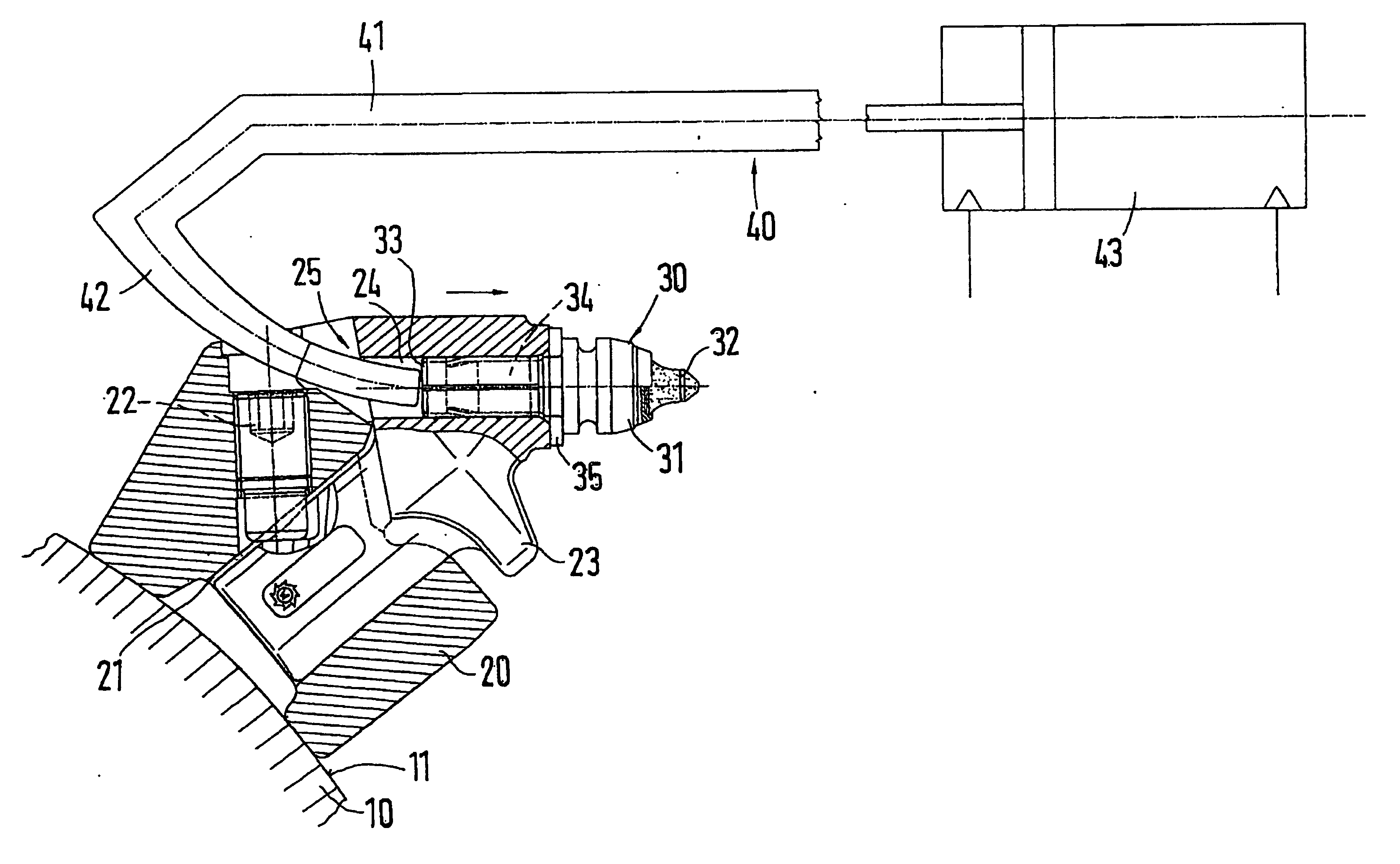
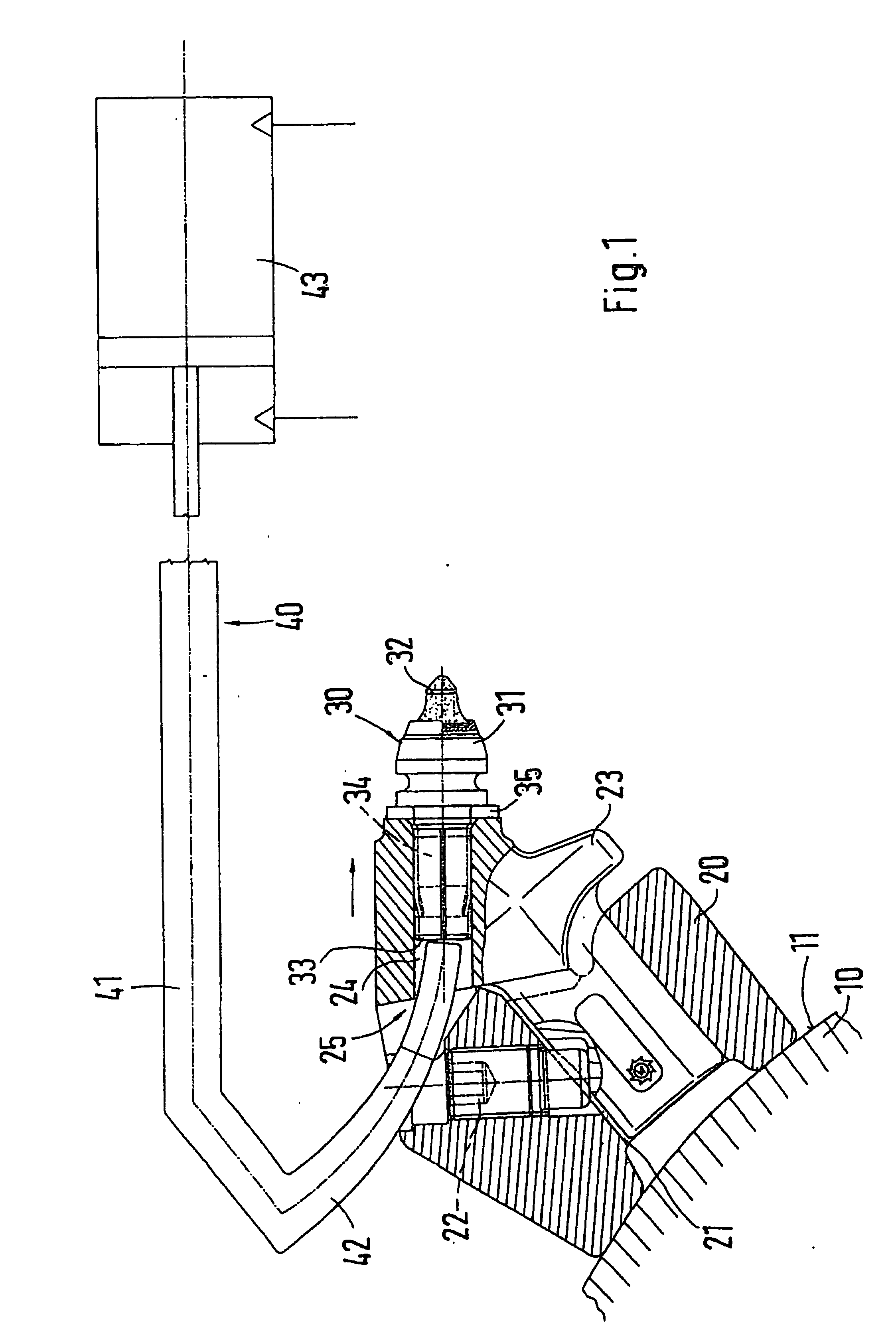
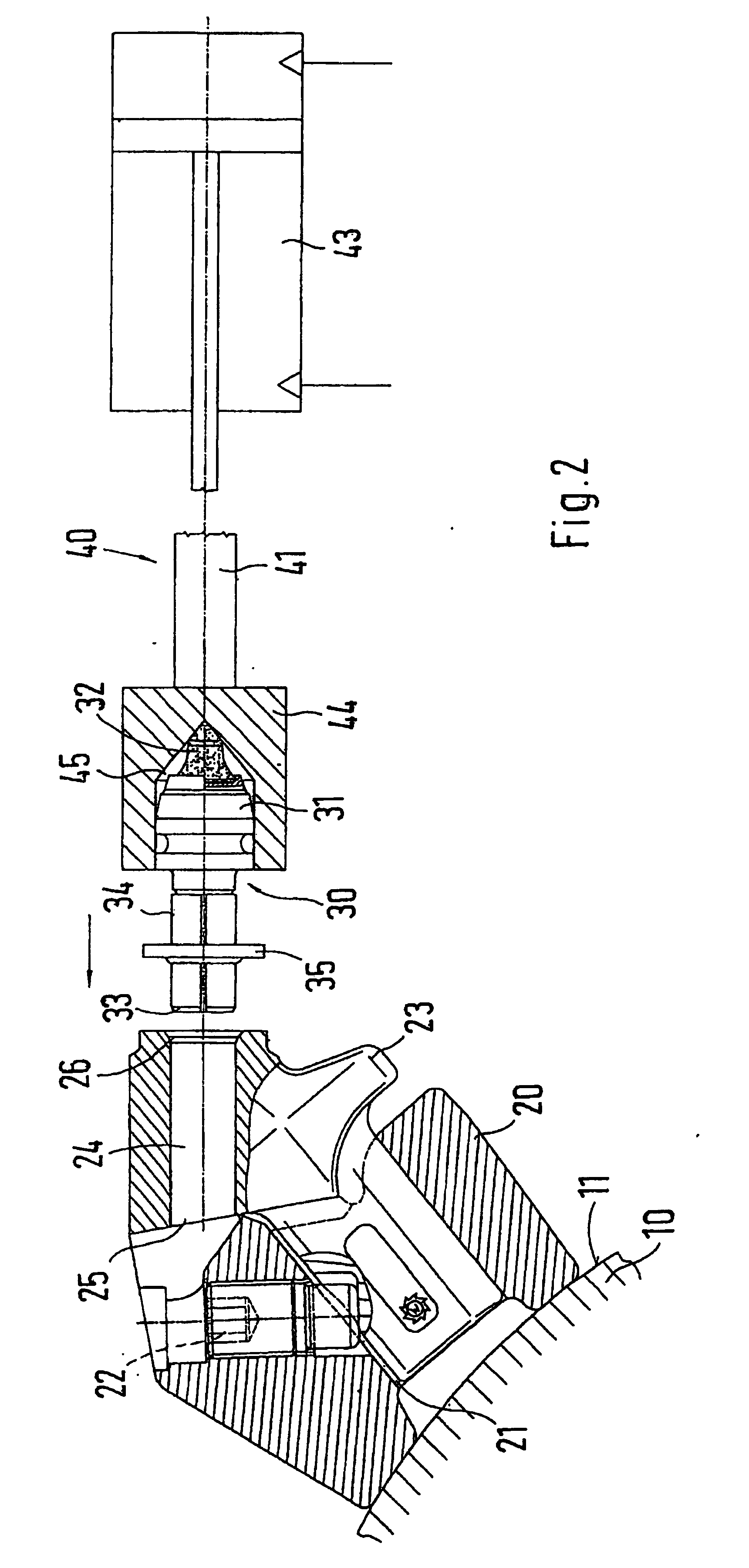
[0026] A rotary body of a road-milling machine, namely a milling roller 10, is represented in FIG. 1. Base elements 20 are arranged in a systematic separation from each other on the roller surface 11 of the milling roller 10. The base elements 20 are connected, preferably welded, to the roller surface 11. The base elements 20 each has a plug-in receiver 21. A plug-in shoulder of a chisel holder 23 can be inserted into the plug-in receiver 21. The chisel holder 23 is fixed on the base element 20 by a pressure screw 22. The chisel holder 23 has a chisel receiver 24, which is embodied as a bore in the present case. A chisel 30, here a round shaft chisel, can be inserted into the bore. The chisel 30 has a chisel head 31, to the front of which a chisel tip 32, comprising a hard alloy or a ceramic material, is fastened. A shaft 33, on which a clamping sleeve 34 is drawn, adjoins the chisel head 31. The clamping sleeve 34 is connected with the shaft 33 so that it is not axially displaceabl...


PUM

PropertyMeasurementUnit
Weightaaaaaaaaaa
Forceaaaaaaaaaa
Torqueaaaaaaaaaa

Abstract

A construction machine for machining floor surfaces, wherein the machine includes a milling roll having a plurality of tool holders on a surface thereof. A tool, especially a straight shank tool, is received in a tool receiving element of the tool holder in an exchangeable manner. With this invention it is possible to change the tool in one such construction machine in a simplified manner. Thus, the milling roll is associated with a tool changing device, and the tool changing device dismounts each tool from the tool holder and/or mounts each tool in the tool holder.

Description

BACKGROUND OF THE INVENTION [0001] 1. Field of the Invention [0002] This invention relates to a construction machine for working pieces of ground, having a milling roller on which surface chisel holders are arranged, wherein a chisel, in particular a round shaft chisel, is exchangeably received in a chisel receiver of the chisel holder. [0003] 2. Discussion of Related Art [0004] A construction machine designed as a road-milling machine is taught by German Patent Reference DE 39 03 482 A1. Road coverings can be cut off by road-milling machines. The chisels continuously wear out during operation of the machine. After the chisels have reached a certain wear state, they must be replaced. Thus it is necessary for a worker to approach the milling roller and there drive the chisels out of the chisel holders. For driving the chisels out, the worker uses a special ejection mandrel and a hammer. This can lead to injuries. Manipulation in the narrow milling roller area is extremely difficult a...

Claims


Application Information

Patent Timeline
IPC IPC(8): E21C25/00B28D1/18E01C23/088E21C35/18
CPCB28D1/188E01C23/088E21C35/18E21C2035/1826E21C35/188
Inventor HOLL, BERNDHAHN, GUNTERLENZ, MARTIN
Owner WIRTGEN GMBH
Why Eureka
Try Eureka