Small-sized low-power dissipation short-range radar that can arbitrarily change delay time between transmission and reception with high time resolution and method of controlling the same

a short-range radar, low-power dissipation technology, applied in the field of short-range radar, can arbitrarily change the delay time between transmission and reception with high time resolution, and control the same, and achieve the effects of low power dissipation, simple configuration, and high time resolution

Inactive Publication Date: 2007-06-14
ANRITSU CORP +1
View PDF2 Cites 52 Cited by
  • Summary
  • Abstract
  • Description
  • Claims
  • Application Information

AI Technical Summary

Benefits of technology

[0148] In such a manner, in a configuration according to a short-range radar of the present invention and a method of controlling the same, a timing at which a variable-period pulse output from a variable-period pulse generator including a direct digital synthesizer (DDS) has shifted in level first since reception of a search instruction is used as a reference timing, so that a signal that shifts in level at the reference timing or a fixed lapse of time later than the reference timing is generated and output as a transmission trigger signal, a signal that shifts in level at a timing delayed by half a period of the variable-period pulse or its integral mult...

Problems solved by technology

However, to actually realize a short-range radar that uses the UWB and has a hi...

Method used


Image

  • Small-sized low-power dissipation short-range radar that can arbitrarily change delay time between transmission and reception with high time resolution and method of controlling the same
  • Small-sized low-power dissipation short-range radar that can arbitrarily change delay time between transmission and reception with high time resolution and method of controlling the same
  • Small-sized low-power dissipation short-range radar that can arbitrarily change delay time between transmission and reception with high time resolution and method of controlling the same

Examples


first embodiment

[0164] First, a configuration of a short-range radar according to a first embodiment of the present invention will be described.

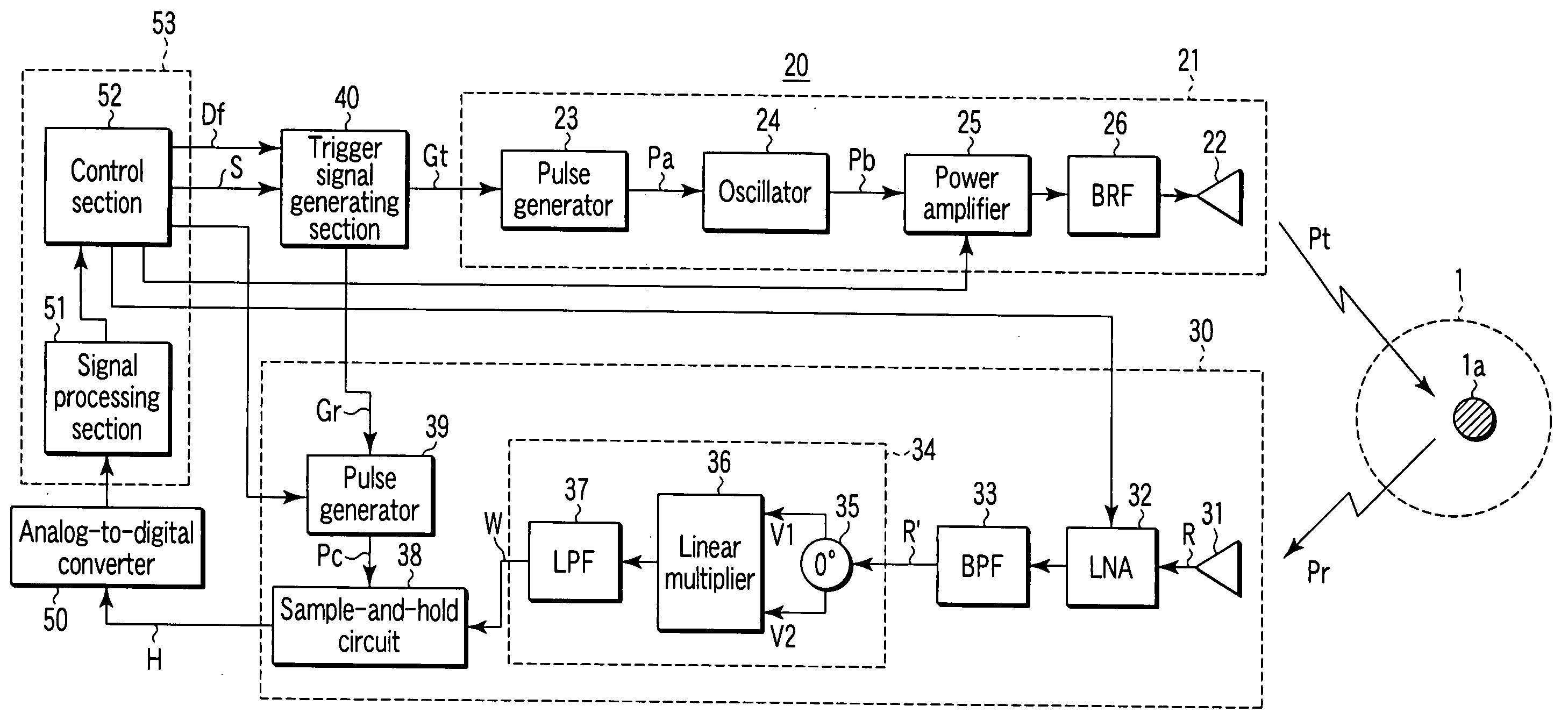
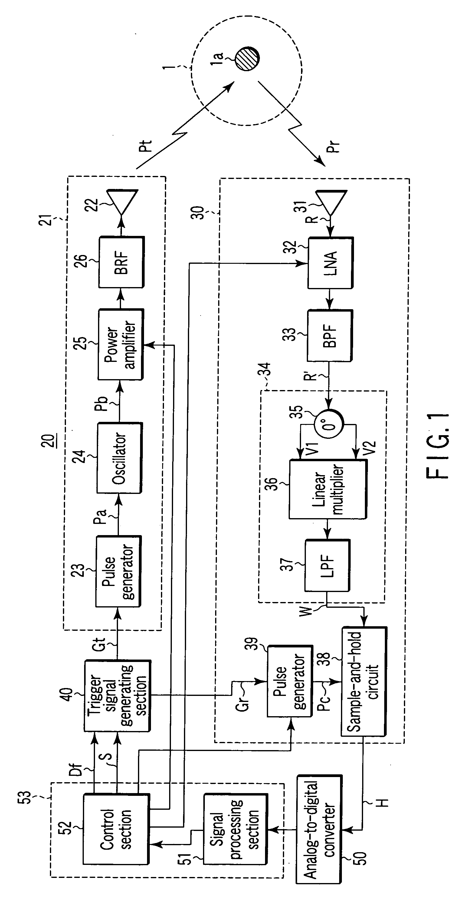
[0165]FIG. 1 is a block diagram showing a configuration of a short-range radar 20 according to the first embodiment of the invention.

[0166] Specifically, the short-range radar 20 shown in FIG. 1 comprises a transmitter section 21, a receiver section 30, a trigger signal generating section 40, an analog-to-digital converter (ADC) 50, a signal processing section 51, and a control section 52.

[0167] Each time receiving a trigger signal Gt output in a predetermined period Tg from the trigger signal generating section 40, the transmitter section 21 radiates via a transmission antenna 22 into space 1 a short pulse wave Pt having a predetermined carrier frequency Fc (e.g., 26 GHz) and a predetermined width Tp (e.g., 1 ns) generated as described later.

[0168] It is to be noted that the transmission antenna 22 is in some cases used together with a reception antenn...

second embodiment

[0281]FIG. 13 is a block diagram showing a specific configuration of a trigger signal generating section 40′ as a configuration of important components of a short-range radar according to a second embodiment of the present invention.

[0282] In FIG. 13, the same components as those in the trigger signal generating section 40 according to the first embodiment shown in FIG. 7 are indicated by the same reference symbols, and explanation of them is omitted.

[0283] In the above-described first embodiment, the fixed delay circuit 43 is provided to reduce to zero a minimum value of delay time from a transmission timing to a reception timing.

[0284] However, if it is unnecessary to search an extremely short-distance region in a search range, it is also possible to omit the fixed delay circuit 43 and use as a transmission trigger signal Gt a first pulse P1 output from the first pulse generation circuit 42 as shown in FIG. 13.

[0285] By thus omitting the fixed delay circuit 43, an influence du...


PUM


Abstract

In a configuration according to a short-range radar of the present invention and a method of controlling the same, the timing at which a variable-period pulse output from a variable-period pulse generator including a direct digital synthesizer (DDS) has shifted in level first since reception of a search instruction is used as a reference timing, so that a signal that shifts in level at the reference timing or a fixed lapse of time later than the reference timing is generated and output as a transmission trigger signal, and a signal that shifts in level at a timing delayed by half a period of the variable-period pulse or its integral multiple from the timing at which the transmission trigger signal is output is generated and output as a reception trigger signal. With this, by varying beforehand frequency data of the DDS based on the relationship between the frequency data and delay time between transmission and reception stored in a memory, it is possible to vary delay time between the transmission trigger signal and the reception trigger signal. It is thus possible to arbitrarily vary the delay time between transmission and reception at a high time resolution by using a simple configuration and low power dissipation.

Description

TECHNICAL FIELD [0001] The present invention relates to a short-range radar and a method of controlling the same, and more specifically, to a short-range radar employing a technology that can realize a short-range radar for use in an ultra-wide band (UWB) of 22 to 29 GHz allocated to automotive radars or walking assist radars for the visually impaired, etc., in a simple and small-sized configuration with low-power dissipation and that can arbitrarily change delay time between transmission and reception with a high time resolution in order to enhance a distance resolution, especially, of those short-range radars for radiating a narrow pulse wave (short pulse wave) into space in a predetermined period and receiving and detecting a reflected wave from an object present in the space to analyze the object based on the detected output; and a method of controlling the same. BACKGROUND ART [0002] A conventionally known pulse radar for searching for an object in space by using a pulse wave b...

Claims


Application Information

Patent Timeline
IPC IPC(8): G01S13/08
CPCG01S7/28G01S13/0209G01S13/10
Inventor UCHINO, MASAHARU
Owner ANRITSU CORP
Why Eureka
Try Eureka