
LED lamp tube

Inactive Publication Date: 2007-06-14
LEDTECH ELECTRONICS CORP
View PDF5 Cites 130 Cited by
  • Summary
  • Abstract
  • Description
  • Claims
  • Application Information

AI Technical Summary

Benefits of technology

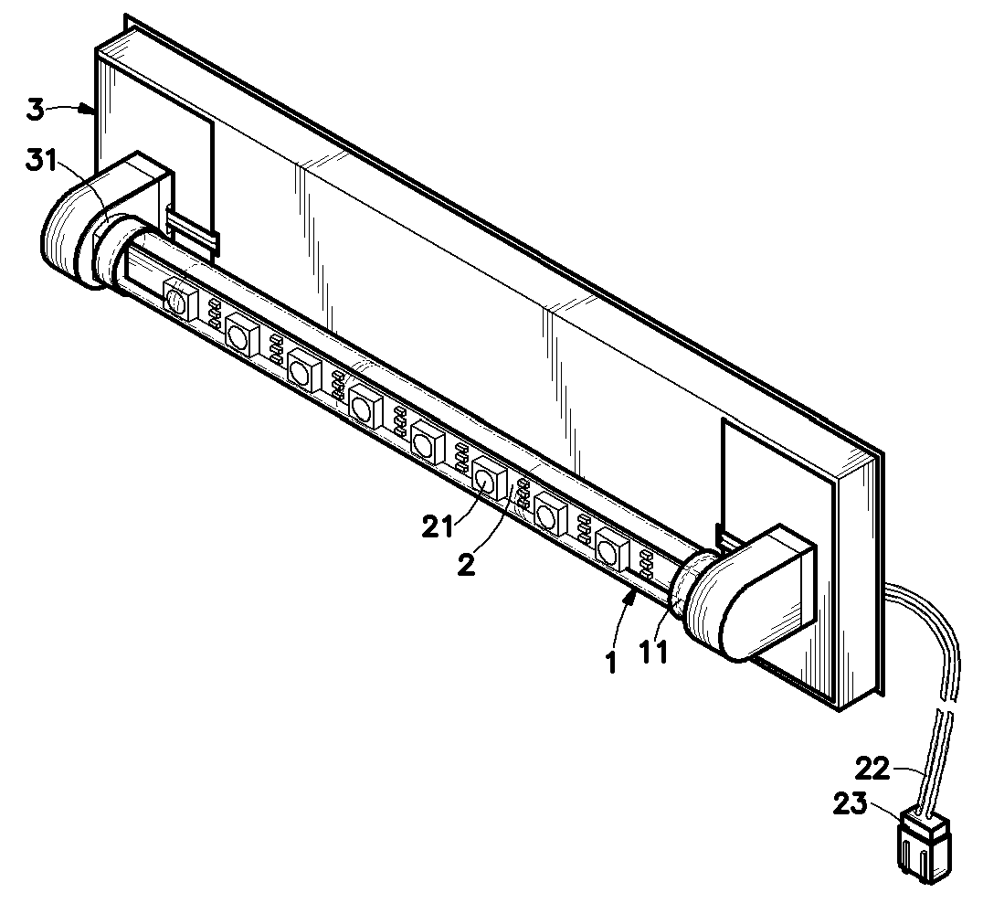
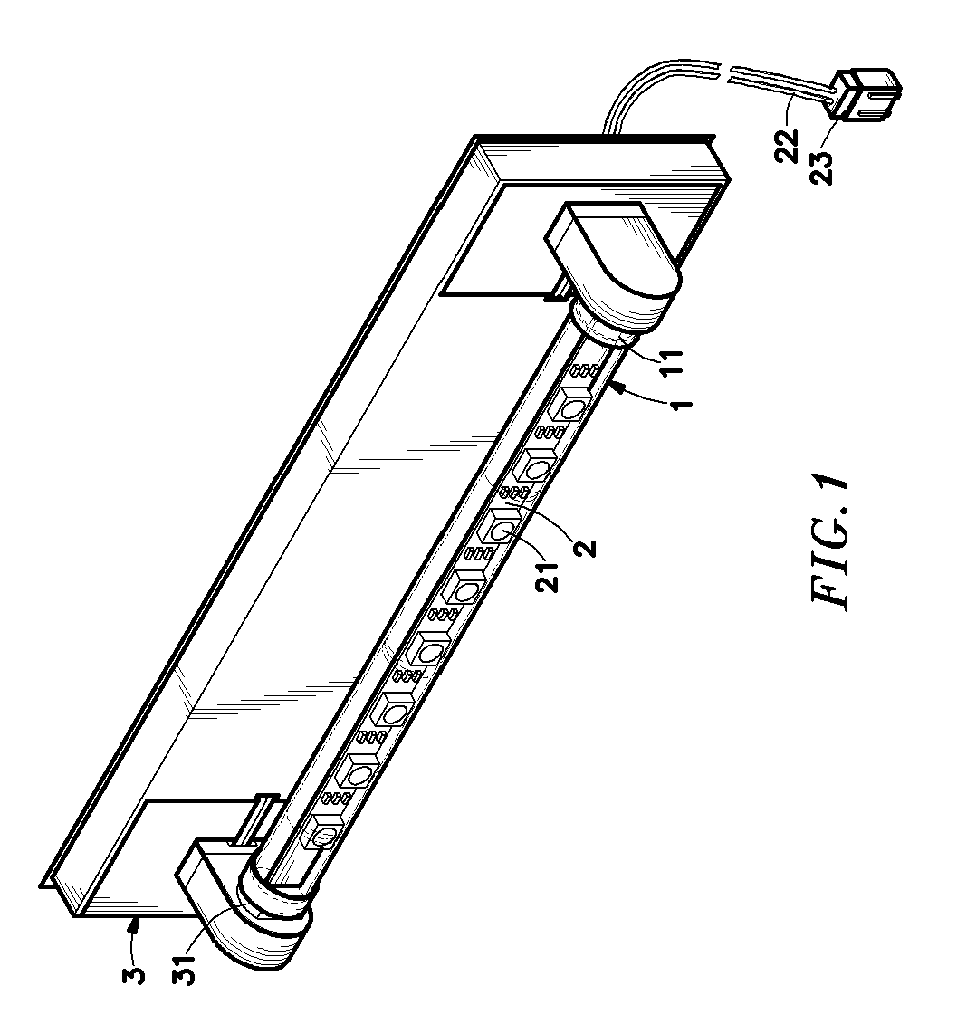
[0006] The present invention has been accomplished under the circumstances in view. It is the main object of the present invention to provide a LED lamp tube, which is directly connectable to a conventional fluorescent bulb holder to substitute for a fluorescent bulb. It is another object of the present invention to provide a LED lamp tube, which has the advantages of quick reaction time, small size, low power consumption, low pollution, high brightness, and long service life. To achieve these and other objects of the present invention, the LED lamp tube comprises a tube that admits light, circuit boards respectively mounted inside the tube, each circuit board carrying an array of LEDs, two end caps respectively capped on the ends of the tube to hold the circuit boards inside the tube and connectable to connectors of a conventional fluorescent bulb holder to secure the tube to the conventional fluorescent bulb holder, and a power cord extending from the circuit boards out of the tube for connection to power supply to obtain the necessary working voltage for the LEDs.

Problems solved by technology

These lighting fixtures have the common drawbacks of high power consumption, quick light attenuation, short service life, fragile characteristic, and being not reclaimable.
Further, during the operation of a fluorescent lamp, electric current passes through the electrodes at a high frequency about 120 times per second, causing sparkling of light that is harmful to the eyes.
However, the high-frequency electronic ballast of a fluorescent lamp is not detachable.
When the fluorescent lamp is damaged, the high-frequency electronic ballast cannot be removed from the fluorescent lamp for a repeat use.

Method used


Image

  • LED lamp tube
  • LED lamp tube
  • LED lamp tube

Examples


Embodiment Construction

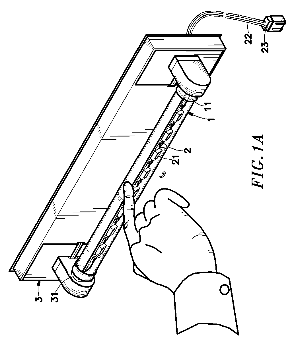
[0013] Referring to FIGS. 1 and 2, a LED lamp tube in accordance with the present invention is shown connectable to connectors 31 of a conventional fluorescent bulb holder 3, comprising a tube 1 and a circuit board 2. The tube 1 can be a transparent or translucent tube in any of a variety of colors, i.e., the tube 1 admits light, having two end caps 111 respectively capped on the two distal ends thereof. The end caps 11 each have mounting pins 111 for installation in the connectors 31 of the fluorescent bulb holder 3. The length of the tube 1 fits the pitch between the connectors 31 of the fluorescent bulb holder 3. The circuit board 2 is a narrow elongated having a plurality of LEDs (light emitting diodes) 21 installed in one side thereof and arranged in an array, and a power cord 22 extending out of one end thereof and terminating in an electric plug 23 for connection to power supply.

[0014] The circuit board 2 is mounted in the tube 1. After insertion of the circuit board 2 into ...


PUM


Abstract

A LED lamp tube is disclosed to include a tube that admits light, circuit boards respectively mounted inside the tube, each circuit board carrying an array of LEDs, two end caps respectively capped on the ends of the tube to hold the circuit boards inside the tube and connectable to connectors of a conventional fluorescent bulb holder to secure the tube to the conventional fluorescent bulb holder, and a power cord extending from the circuit boards out of the tube for connection to power supply to obtain the necessary working voltage for the LEDs.

Description

BACKGROUND OF THE INVENTION [0001] 1. Field of the Invention [0002] The present invention relates to lamps and more particularly, to a LED lamp tube that can directly be installed in a conventional fluorescent bulb holder to substitute for a conventional fluorescent bulb. [0003] 2. Description of the Related Art [0004] The invention of lamp changes the living style of human beings. Without lamp, we cannot work at night or in the dark, and the living standard of human beings will stay in the level of the old time. [0005] Commercial lighting fixtures commonly use fluorescent lamps, incandescent lamps, or the so-called power-saving lamps to give off light for illumination. These lighting fixtures have the common drawbacks of high power consumption, quick light attenuation, short service life, fragile characteristic, and being not reclaimable. Further, during the operation of a fluorescent lamp, electric current passes through the electrodes at a high frequency about 120 times per secon...

Claims


Application Information

Patent Timeline
IPC IPC(8): F21V1/00F21V11/00
CPCF21K9/17F21S8/031F21Y2101/02F21Y2103/003F21Y2111/005Y02B20/386F21K9/58Y10S362/80F21K9/65F21Y2103/10F21Y2115/10F21Y2107/30F21K9/272Y02B20/30
Inventor HUANG, MING-CHUNGLIU, YU-YANGOU, FU-HSUNGCHEN, YING-HSUAN
Owner LEDTECH ELECTRONICS CORP
Learn More