

Hydraulic accumulator
- Summary
- Abstract
- Description
- Claims
- Application Information
AI Technical Summary
Benefits of technology
Problems solved by technology
Method used
Image

Examples
Embodiment Construction
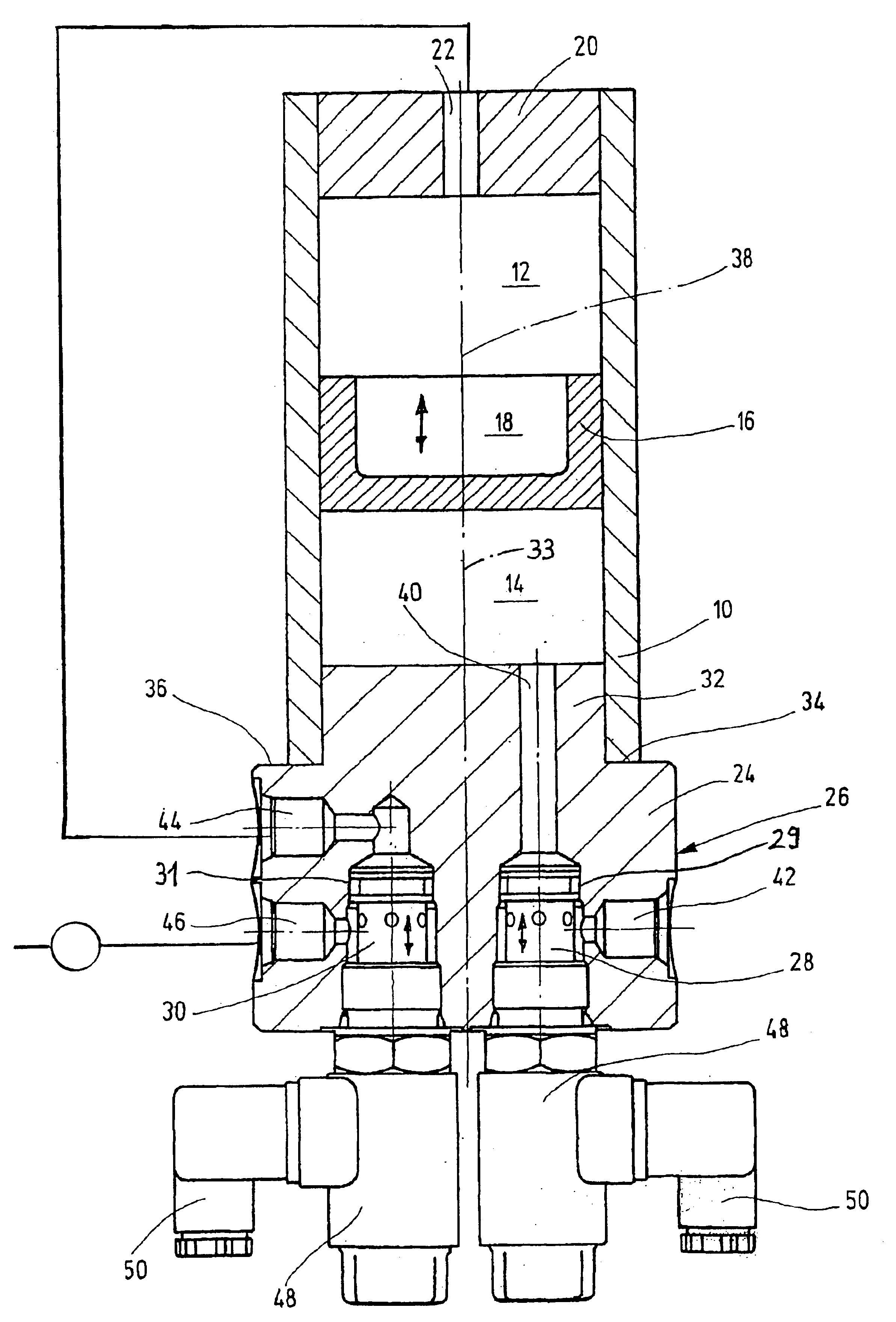
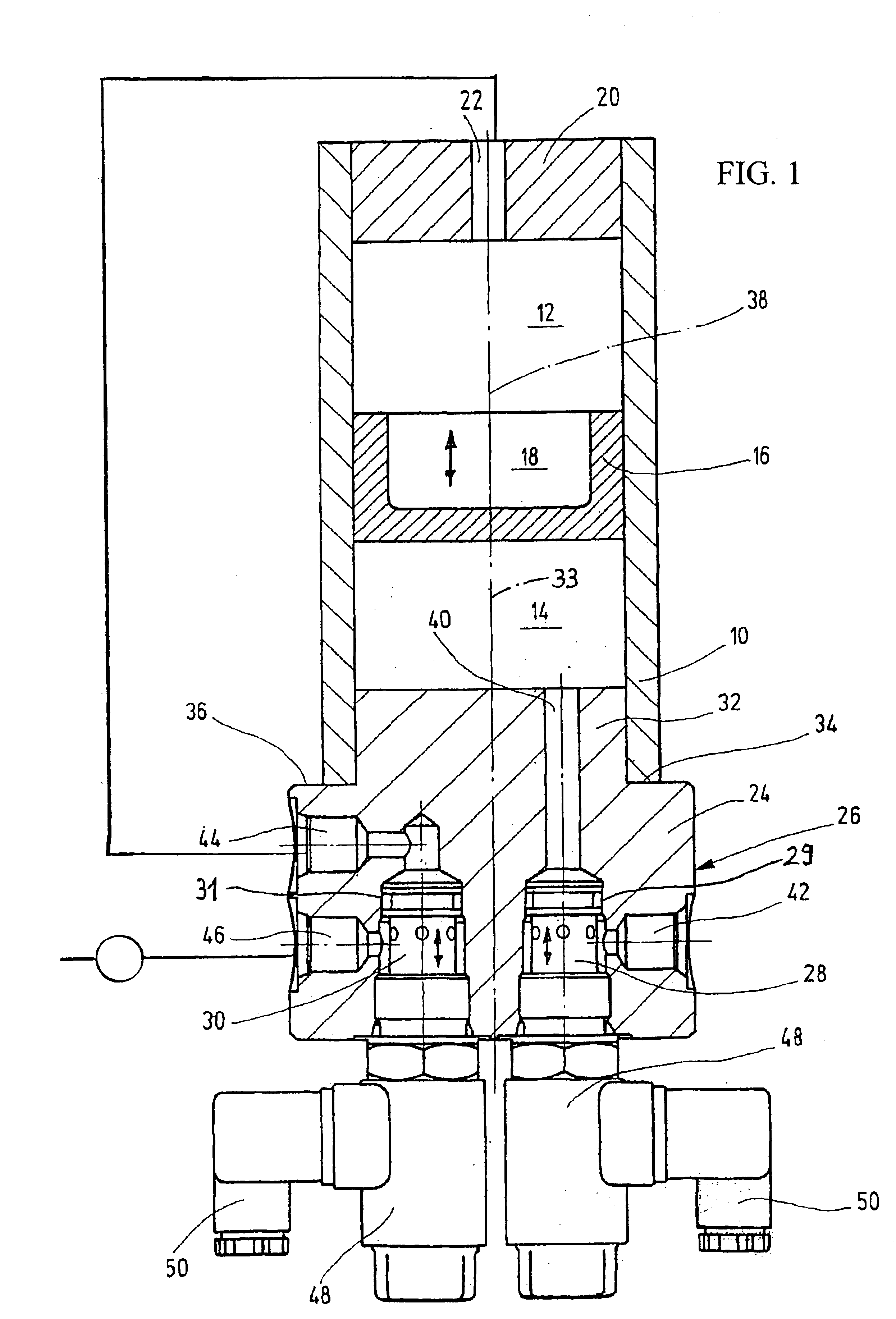
The illustrated hydraulic accumulator is designed as a piston accumulator. This accumulator has an accumulator housing 10 with a gas chamber 12 and a fluid chamber 14 located in the housing. The gas chamber 12 is separated from the fluid chamber 14 by a separating element 16 in the form of a piston part. The separating element can be moved longitudinally along the inside circumference or surface of the accumulator housing 10 (as indicated by the double-headed arrow therein) so that the spatial relationship between the gas chamber 12 and the fluid chamber 14 is kept variable. In order to be able to store a large quantity of working gas in the gas chamber 12, the separating element 16 is designed as a hollow part. Its inside has a corresponding recess 18. In the direction of the illustration, the gas chamber 12 is closed at the top by a cover part 20 having a center hole 22. The working gas, for example, nitrogen gas, can be brought into the gas chamber 12 through the center hole. The...
PUM
 Abstract
Description
Claims
Application Information