
Method for reconstructing three-dimensional structure using silhouette information in two-dimensional image

a two-dimensional image and three-dimensional structure technology, applied in the field of three-dimensional structure reconstruction using silhouette information in two-dimensional image, can solve the problems of difficult reconstruction of the three-dimensional structure of a moving object in real-time, long processing time, and mass amount of computation of conventional voxel carving methods, and achieve the effect of quick reconstruction

Inactive Publication Date: 2007-06-14
ELECTRONICS & TELECOMM RES INST
View PDF7 Cites 29 Cited by
  • Summary
  • Abstract
  • Description
  • Claims
  • Application Information

AI Technical Summary

Benefits of technology

The present invention provides a method for reconstructing a three-dimensional structure using silhouette information on a two-dimensional image plane. The method involves creating a cube on a three-dimensional space by extracting silhouette images from multiple cameras and calculating vertex coordinates on a two-dimensional image plane. The cube is then divided into inner voxels and regions for easier handling. Common indices are found through repeatedly performing the steps and used to reconstruct the three-dimensional structure. The technical effect of the invention is to enable quick and efficient reassembly of three-dimensional structures using a small amount of computation.

Problems solved by technology

However, it is very difficult to reconstruct the three-dimensional structure of a moving object in real-time.
However, the conventional voxel carving methods still require mass amount of computation and a long processing time because it must calculate an inverse matrix that is created when the silhouette is backwardly projected on a three-dimensional space.

Method used


Image

  • Method for reconstructing three-dimensional structure using silhouette information in two-dimensional image
  • Method for reconstructing three-dimensional structure using silhouette information in two-dimensional image
  • Method for reconstructing three-dimensional structure using silhouette information in two-dimensional image

Examples


Embodiment Construction

[0026] Other objects and advantages of the present invention will become apparent from the following description of the embodiments with reference to the accompanying drawings. Therefore, those skilled in the art that the present invention is included can embody the technological concept and scope of the invention easily. In addition, if it is considered that detailed description on a related art may obscure the points of the present invention, the detailed description will not be provided herein. The preferred embodiments of the present invention will be described in detail hereinafter with reference to the attached drawings.

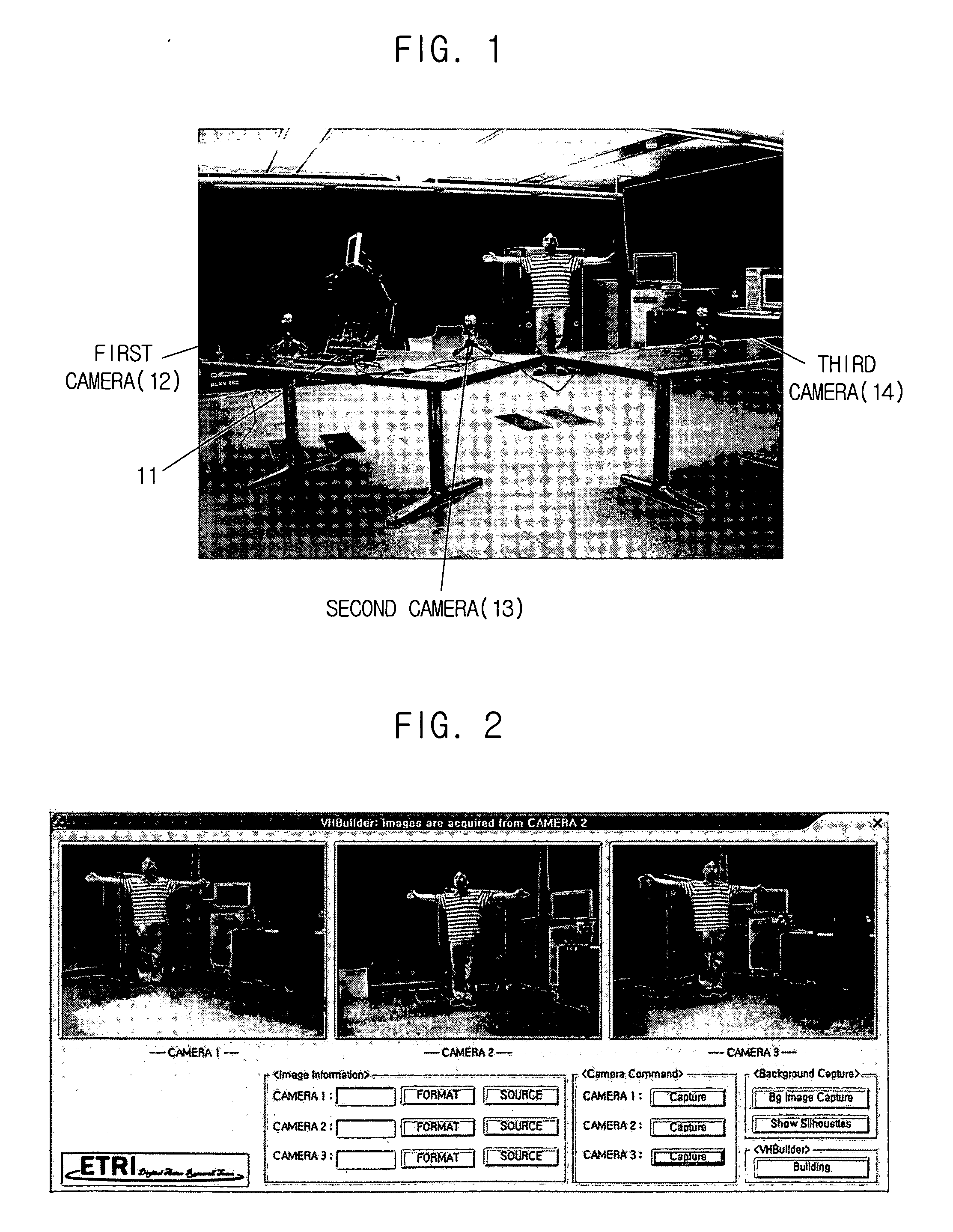
[0027]FIG. 1 is a view showing a method for controlling three USB web cameras in a personal computer PC where the present invention is applied.

[0028] The personal computer PC includes at least three universal serial bus (USB) controllers. Each of the USB controllers has a fixed bandwidth. Generally, a USB web camera has about 50 to 70% of bandwidth. Therefore...


PUM


Abstract

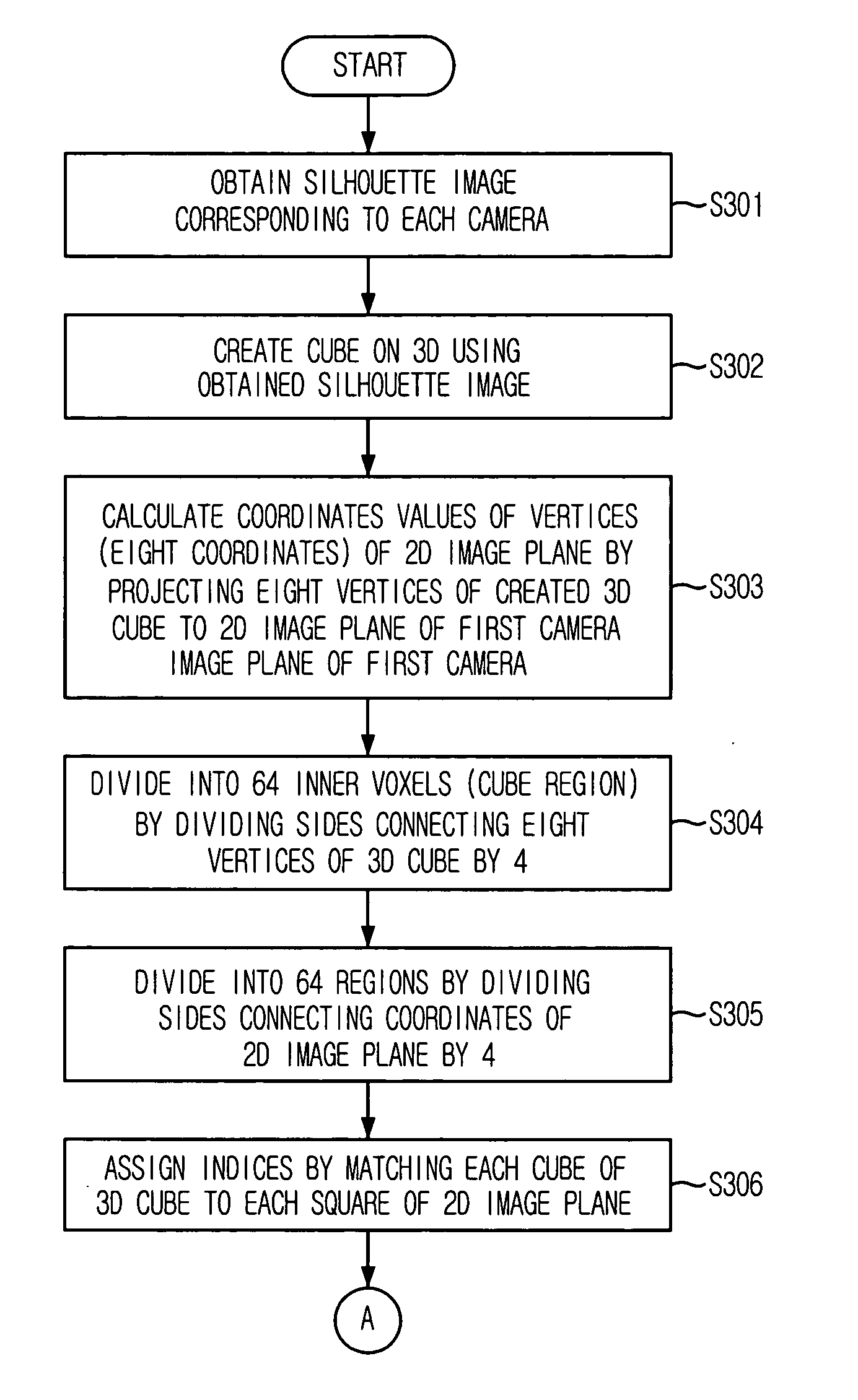
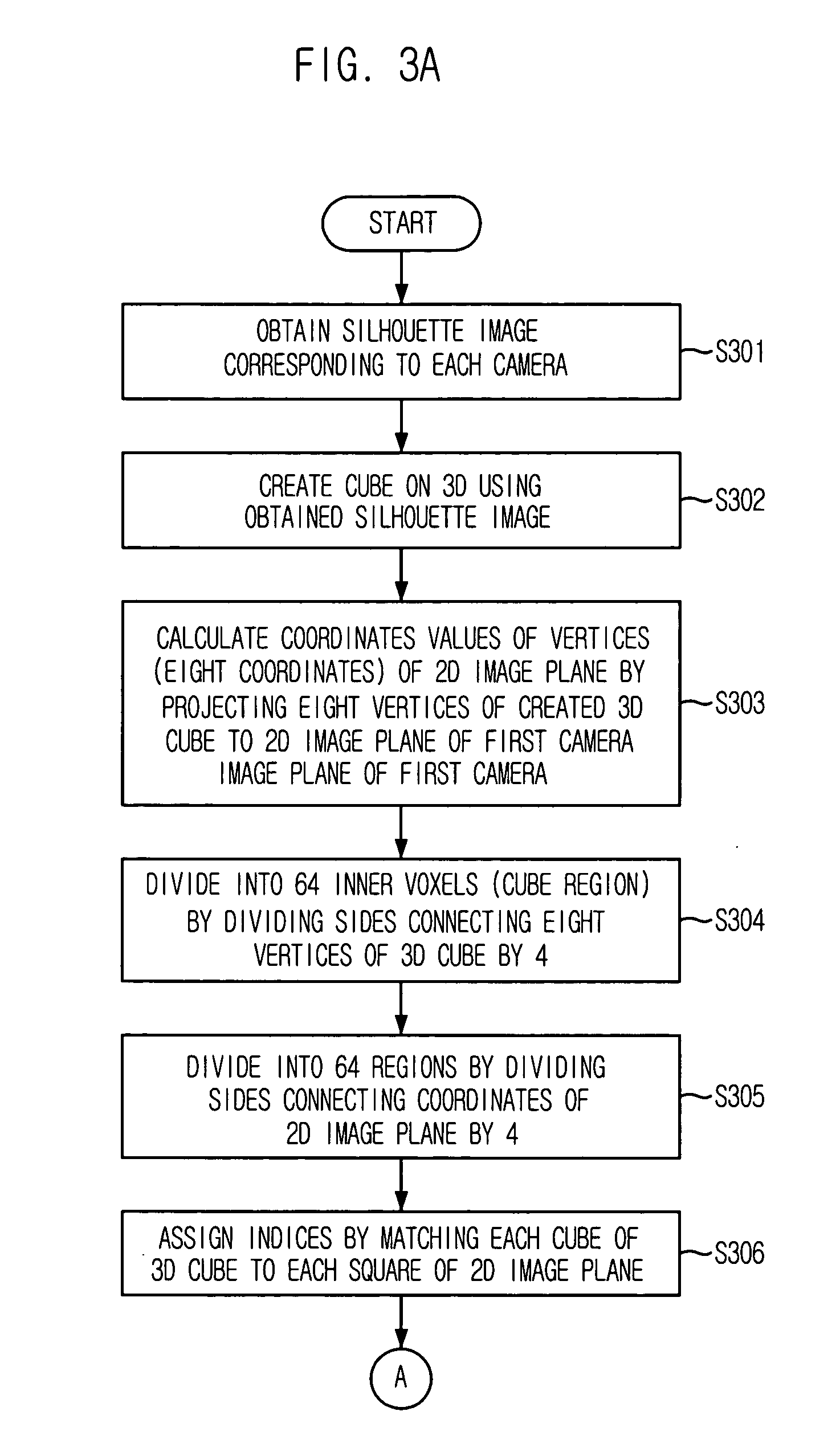
A method for reconstructing a three-dimensional structure using silhouette information on a two-dimensional plane is provided. The method includes: obtaining silhouette images; creating a cube on a three-dimensional space using the silhouette images; calculating vertex coordinates on a two-dimensional image plane by projecting eight vertices of the three-dimensional cube on a two-dimensional image plane of a first camera; dividing into multiple inner voxels by dividing sides formed by the eight vertices by a divider; dividing into a predetermined number of regions by dividing sides connecting the coordinates by a predetermined divider; assigning indices by matching cubes of the three-dimensional cube to square regions on the two-dimensional image plane in one to one manner; storing indices of regions where the square regions meets with a first silhouette image; and reconstructing three-dimensional structure by finding common indices through repeatedly performing the steps using other silhouette images.

Description

FIELD OF THE INVENTION [0001] The present invention relates to a method for reconstructing a three dimensional structure using silhouette information in a two-dimensional image; and, more particularly, to a method for reconstructing a three-dimensional structure using silhouette information in a two-dimensional image by creating a cube on a three dimensional space after extracting silhouette information from images captured through a plurality of cameras and projecting eight vertices of the three-dimensional cube on an image plane. DESCRIPTION OF RELATED ART [0002] In an embodiment of the present invention, three cameras are used. However, the present invention is not limited by the number of the cameras. [0003] In order to develop technology for reconstructing a three-dimensional object, many researches have been conducted on reconstructing or recognizing the structure of a real scene or the shape of an object in a robot vision system or a machine vision system. The three-dimension...

Claims


Application Information

Patent Timeline
Patent Type & Authority Applications(United States)
IPC IPC(8): G06K9/00G06V10/10
CPCG06K9/20G06K2209/40G06V10/10G06V2201/12G06T17/10G06T17/00
Inventor LEE, JAE-KWANGPARK, CHANG-JOONLEE, IN-HOKIM, HYUN-BIN
Owner ELECTRONICS & TELECOMM RES INST
Learn More