Fuel cell compressor system

a fuel cell and compressor technology, applied in the direction of piston pumps, marine propulsion, vessel construction, etc., can solve the problems of high-speed motor use, complex oil lubrication system, inefficient use,

Inactive Publication Date: 2007-06-14
EATON CORP
View PDF11 Cites 31 Cited by
  • Summary
  • Abstract
  • Description
  • Claims
  • Application Information

AI Technical Summary

Problems solved by technology

However, the use of high-speed motors can involve some disadvantages.
Among other things, sealed, greased bearings are commonly unable to adequately operate at such higher motor speeds.
Also, while open oil bearings may operate at higher compressor speeds, their use requires inefficient, complex, oil lubrication systems to survive.
Further, while air bearings can sometimes be used in higher-speed environments, and operate cleanly, such bearings are often expensive and impractical for mass production.

Method used


Image

  • Fuel cell compressor system
  • Fuel cell compressor system
  • Fuel cell compressor system

Examples


Embodiment Construction

[0017] Reference will now be made in detail to embodiments of the present invention, examples of which are illustrated in the accompanying drawings. While the invention will be described in conjunction with the embodiments, it will be understood that they are not intended to limit the invention to these embodiments. On the contrary, the invention is intended to cover alternatives, modifications and equivalents, which may be included within the spirit and scope of the invention as embodied in or defined by the appended claims.

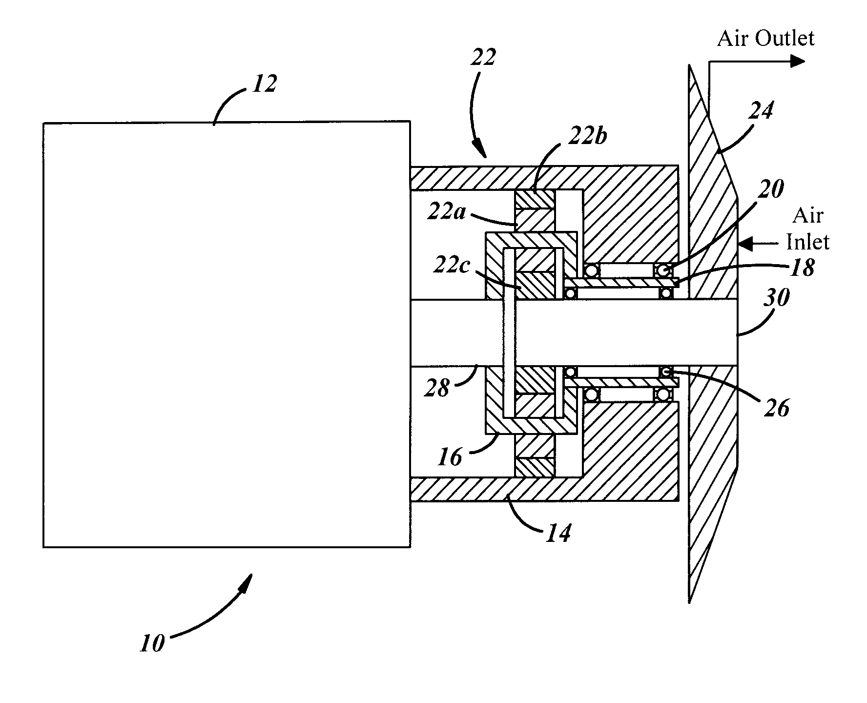
[0018]FIG. 1 generally illustrates a cross-sectional view of a fuel cell compressor system 10 in accordance with an embodiment of the invention. The illustrated system 10 is shown including a motor 12, a drive housing 14, a first gear set 16, carrier torque tube 18, first bearing 20, a second gear set 22, impeller 24, and a second bearing 26. Embodiments of the system, of the type shown in FIG. 1, are sometimes referred to as “single-stage” compressor systems. ...


PUM


Abstract

The invention provides a fuel cell compressor system that comprises a motor, including a motor shaft driven by the motor; a drive housing at least partially surrounding the motor shaft; a first gear set driven by the motor shaft; a carrier torque tube driven by the first gear set; and an impeller. The impeller includes an impeller shaft driven by the second gear set, so that the impeller shaft is configured to rotate at a speed greater than motor speed. Embodiments of the invention may also be used with a multi-stage compressor that allows, for example, first and second impellers to rotate at different speeds. Embodiments of the invention may also include removal of a gear set driving the carrier torque tube or the impeller shaft, so that the impeller shaft speed is divided between one or more bearings supporting the carrier torque tube and one or more bearings supporting the impeller shaft.

Description

RELATED APPLICATIONS [0001] This application claims the benefit of U.S. Provisional Patent Application No. 60 / 750,225 filed Dec. 14, 2005, hereby incorporated by reference in its entirety.BACKGROUND OF INVENTION [0002] a. Field of Invention [0003] The invention relates generally to a fuel cell compressor system, including a fuel cell compressor system that uses a gear set configured to drive an impeller at a speed greater than motor speed. [0004] b. Description of Related Art [0005] Fuel cells generally require clean, pressurized fluid to operate reliably. Centrifugal compressors designed for low flow, operate more efficiently at higher speeds. Accordingly, conventional centrifugal fuel cell compressors are typically directly driven by high-speed motors. However, the use of high-speed motors can involve some disadvantages. Among other things, sealed, greased bearings are commonly unable to adequately operate at such higher motor speeds. Also, while open oil bearings may operate at h...

Claims


Application Information

Patent Timeline
Patent Type & Authority Applications(United States)
IPC IPC(8): F04B17/00
CPCF04D25/028H01M8/04111Y02E60/50
Inventor EYBERGEN, WILLIAMPRYOR, MARTINBROWN, JAMES
Owner EATON CORP
Why Eureka
Try Eureka