
Control method of refrigerator

a technology of refrigerator and control method, which is applied in the direction of ice production, domestic cooling apparatus, lighting and heating apparatus, etc., can solve the problems of deteriorating the capacity of the ice maker's ice maker per day, affecting the quality of the ice, and the speed of making ice in the ice-making tray becomes slowed, so as to improve the ice-making method, improve the ice-making structure, and produce a large quantity of ice in a shor

Active Publication Date: 2007-06-21
YALE UNIV +1
View PDF12 Cites 76 Cited by
  • Summary
  • Abstract
  • Description
  • Claims
  • Application Information

AI Technical Summary

Benefits of technology

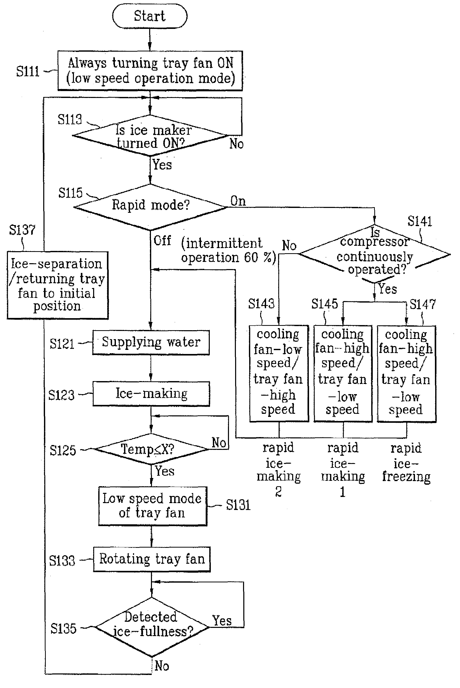
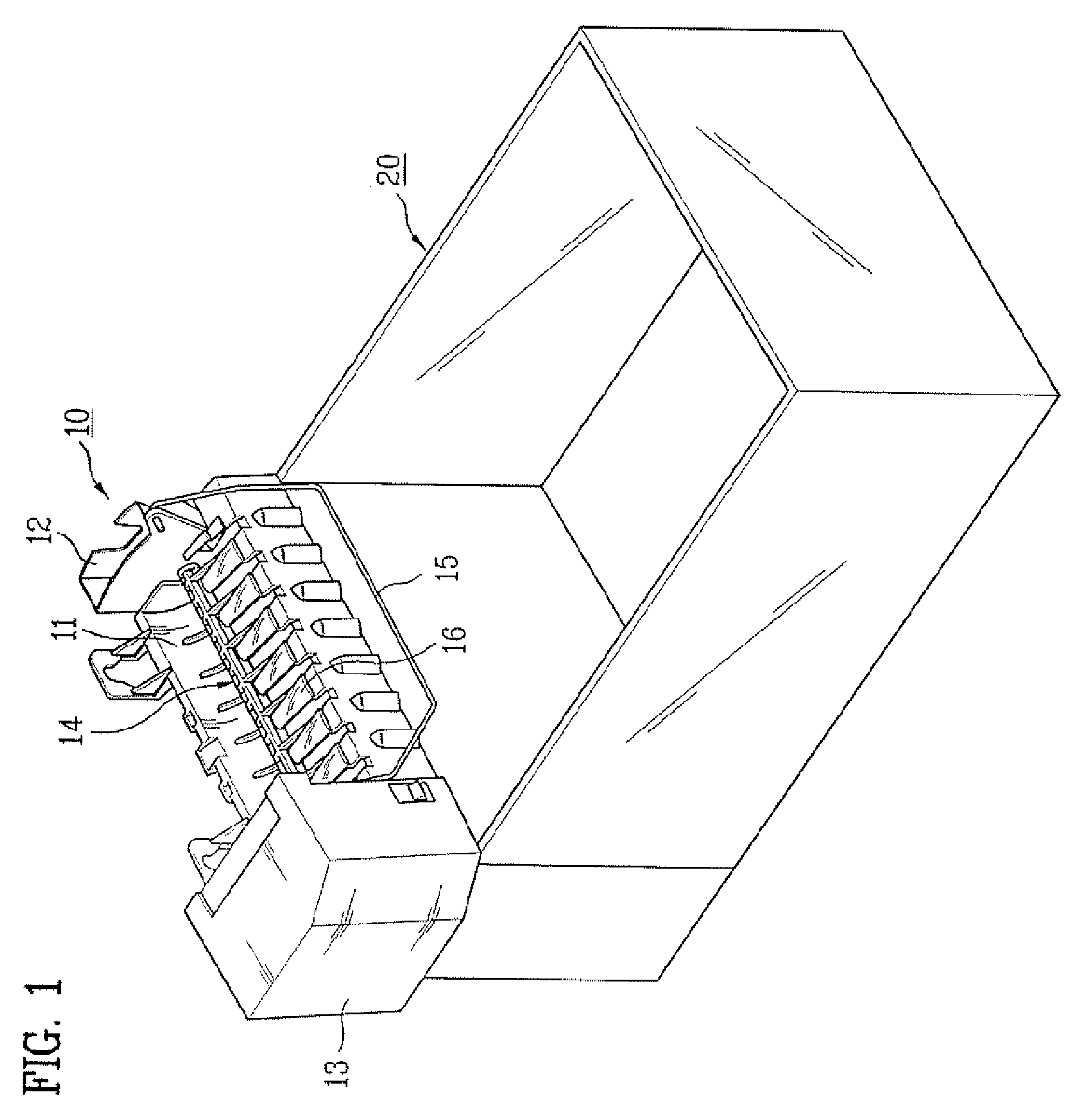
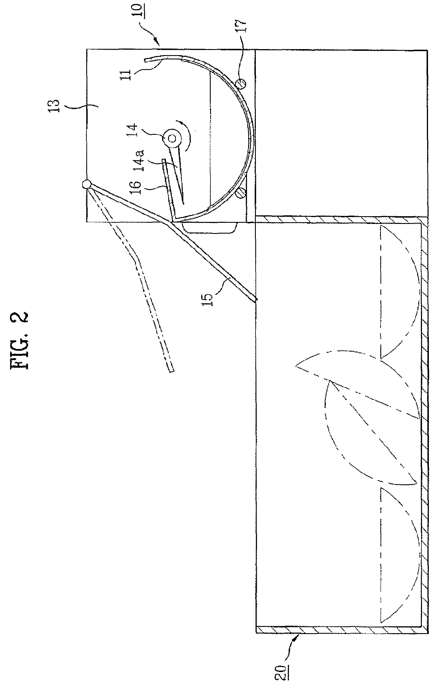
The present invention provides an improved ice-making structure and method for producing a large amount of ice quickly. The ice-making structure includes an ice-making tray and a fan for circulating air to the tray. The fan may be installed on the bottom of the tray. The method includes supplying chilled air to the compartment and blowing it onto the ice-making tray regardless of conditions in the compartment. The blowing speed of the air may be adjusted based on the demand. The chilled air may be continuously blown to the ice-making tray during the operation of the refrigerator. The fan may be rotated at low or high speed depending on the demand for rapid ice-making. The method may also include intermittently or continuously operating the compressor of the refrigerator and / or determining whether rapid ice-making is demanded and adjusting the rotation speed of the fan accordingly. The ice maker may also include a plurality of passages on the surface of the ice-making tray. The technical effects of the invention include improved ice-making speed and efficiency, reduced energy consumption, and improved control over ice-making process.

Problems solved by technology

Thus, when temperature of the freezer compartment descends and the chilled air is stopped to supply to the freezer compartment, the speed of making ice in the ice-making tray become slowed.
Due to this, the capacity of quantity of ice made per day of the ice maker is deteriorated.
Moreover, when a large quantity of ice is required in a short time, the demand cannot be satisfied.
Thus, since a wide space for the rotation of the ice-fullness sensor should be secured beside the ice-making tray, the size of the ice-making tray must be relatively small so that it is difficult to produce a large quantity of ice.

Method used


Image

  • Control method of refrigerator
  • Control method of refrigerator
  • Control method of refrigerator

Examples


Embodiment Construction

[0051]Reference will now be made in detail to the preferred embodiments of a method of controlling a refrigerator and an ice maker, examples of which are illustrated in FIGS. 3 to 10.

[0052]FIG. 3 schematically shows a refrigerator according to a preferred embodiment of the present invention. The refrigerator according to the preferred embodiment of the present invention includes at least one compartment, for example, a refrigerator compartment 1 and a freezer compartment 2. The refrigerator further includes an evaporator 4, a compressor 3, and a cooling fan 5 for supplying chilled air around the evaporator 4 to the compartments. Here, the compartments may be refrigerated by a single evaporator 4 and a single cooling fan 5, or may be independently refrigerated by a plurality of evaporators and a plurality of cooling fans. In the freezer compartment 2, an ice maker 100 according to the preferred embodiment of the present invention is provided to produce ice. Under the ice maker 100, a...


PUM


Abstract

A method of controlling a refrigerator including an ice maker for making ice using chilled air is disclosed. The method includes supplying chilled air to a compartment, blowing chilled air in the compartment to an ice-making tray disposed in the compartment regardless of conditions in the compartment, and varying a blowing speed of the chilled air in the compartment to the ice-making tray according to a demand. According to the present invention, a large quantity of ice can be produced within a short time. Ice-making speed and the quantity of ice can be varied according to a user's demand.

Description

[0001]This application claims the benefit of Korean Patent Application No. P05-324876, filed on Dec. 16, 2005, which is hereby incorporated by reference as if fully set forth herein.BACKGROUND OF THE INVENTION[0002]1. Field of the Invention[0003]The present invention relates to a refrigerator, and more particularly, to a method of controlling a refrigerator including an ice maker for making ice using chilled air.[0004]2. Discussion of the Related Art[0005]Generally, a refrigerator is partitioned into a refrigerator compartment and a freezer compartment. The refrigerator compartment is maintained about at 3 degrees centigrade to 4 degrees centigrade such that food and vegetables can be stored in good condition for a long time, and the freezer compartment is maintained under zero degrees centigrade such that meat and other food can be stored at a frozen state.[0006]Recently, the refrigerator includes various features such as an ice maker, a dispenser, or the like. Described in detail,...

Claims


Application Information

Patent Timeline
Patent Type & Authority Applications(United States)
IPC IPC(8): F25D17/04F25C1/22
CPCF25C5/187F25C2305/022F25C2400/06F25C2400/10F25D2317/0682F25D2317/061F25D2317/0681F25D17/062F25D29/003F25C2600/04F25C2305/0221F25C1/24F25D23/00F25D17/00F25D29/00
Inventor LEE, DONG HOONJEONG, IN CHULKIM, YOUNG JIN
Owner YALE UNIV
Learn More