Construction of transmission gear sleeve with retarded descent function

a transmission gear and function technology, applied in the direction of lifting devices, mechanical devices, gears, etc., can solve the problems of product damage and person injury, and achieve the effects of increasing the friction coefficient of inner balls, reducing the risk of product damage, and prolonging the life of the sleev

Inactive Publication Date: 2007-06-21
WU CHING CHE
View PDF2 Cites 0 Cited by
  • Summary
  • Abstract
  • Description
  • Claims
  • Application Information

AI Technical Summary

Benefits of technology

[0006] According to the second aspect of the present invention, there is provided a new construction of transmission gear sleeve with retarding descent function, two sets of two facing conical spring plates in series design cause extruding outward of spring plate applying a force on two plates type pressure bearing, and then increase the friction coefficient of inner ball, therefore forcing the transmission gear sleeve to the sliding seat revolution tightly.
[0007] According to the third aspect of the present invention, there is provided a new construction of transmission gear sleeve with retarding descent function, one end of the transmission gear sleeve is designed to bolt the ball sleeve transmission member instead of traditional one with plastic material, for special increase of the accuracy of sliding seat up and down movement and its longer life span.

Problems solved by technology

The usually design of a vertical worm driving platform integrate the worm drive with the transmission bushing of sliding seat equipment, the upper and down displacement of platform is driven by the motor on side of the sliding seat, however, owing to the design of transmission bushing with sliding seat adapt bearing set, once system power cut, platform down, the sliding block slips downward with acceleration due to free motion of the driving motor, the accident would cause products damaged and persons harmed, so owner would like to embrace the new one free from this kind of troubles.

Method used


Image

  • Construction of transmission gear sleeve with retarded descent function
  • Construction of transmission gear sleeve with retarded descent function
  • Construction of transmission gear sleeve with retarded descent function

Examples


Embodiment Construction

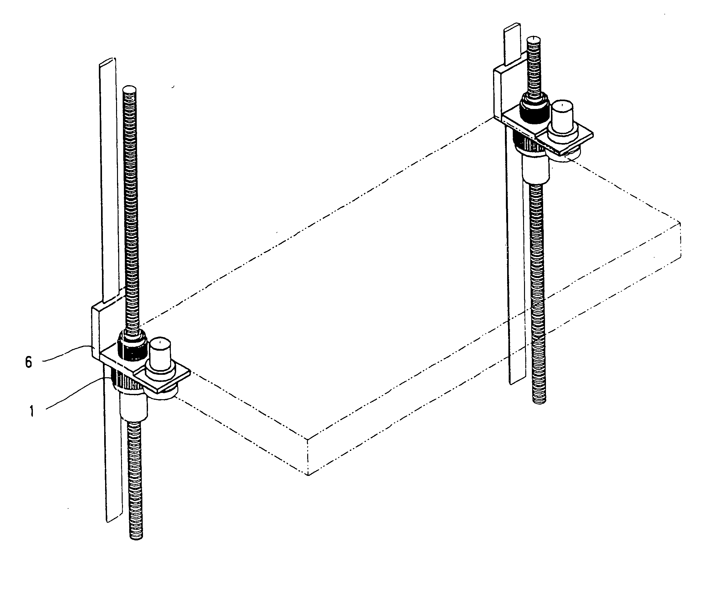
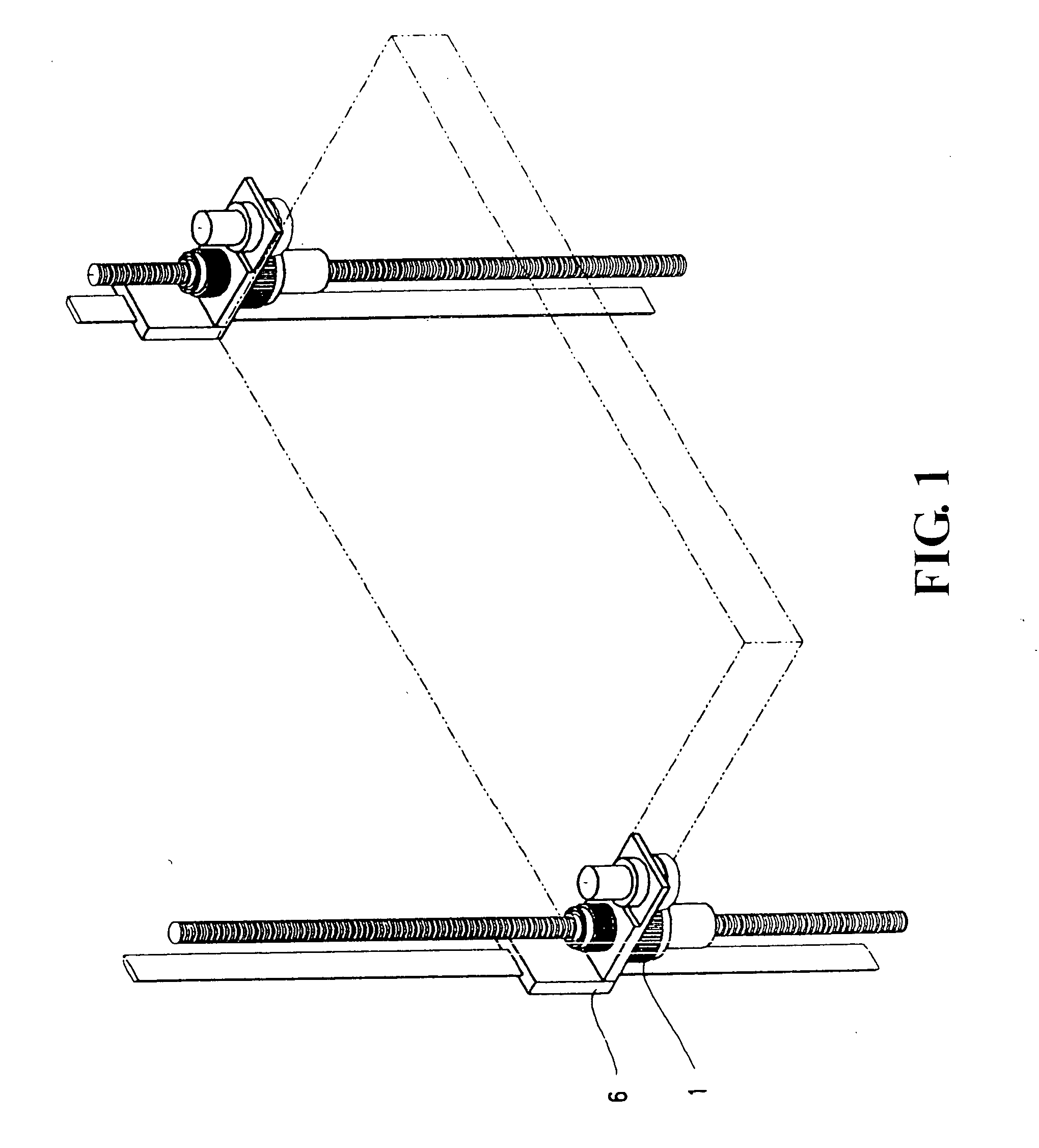
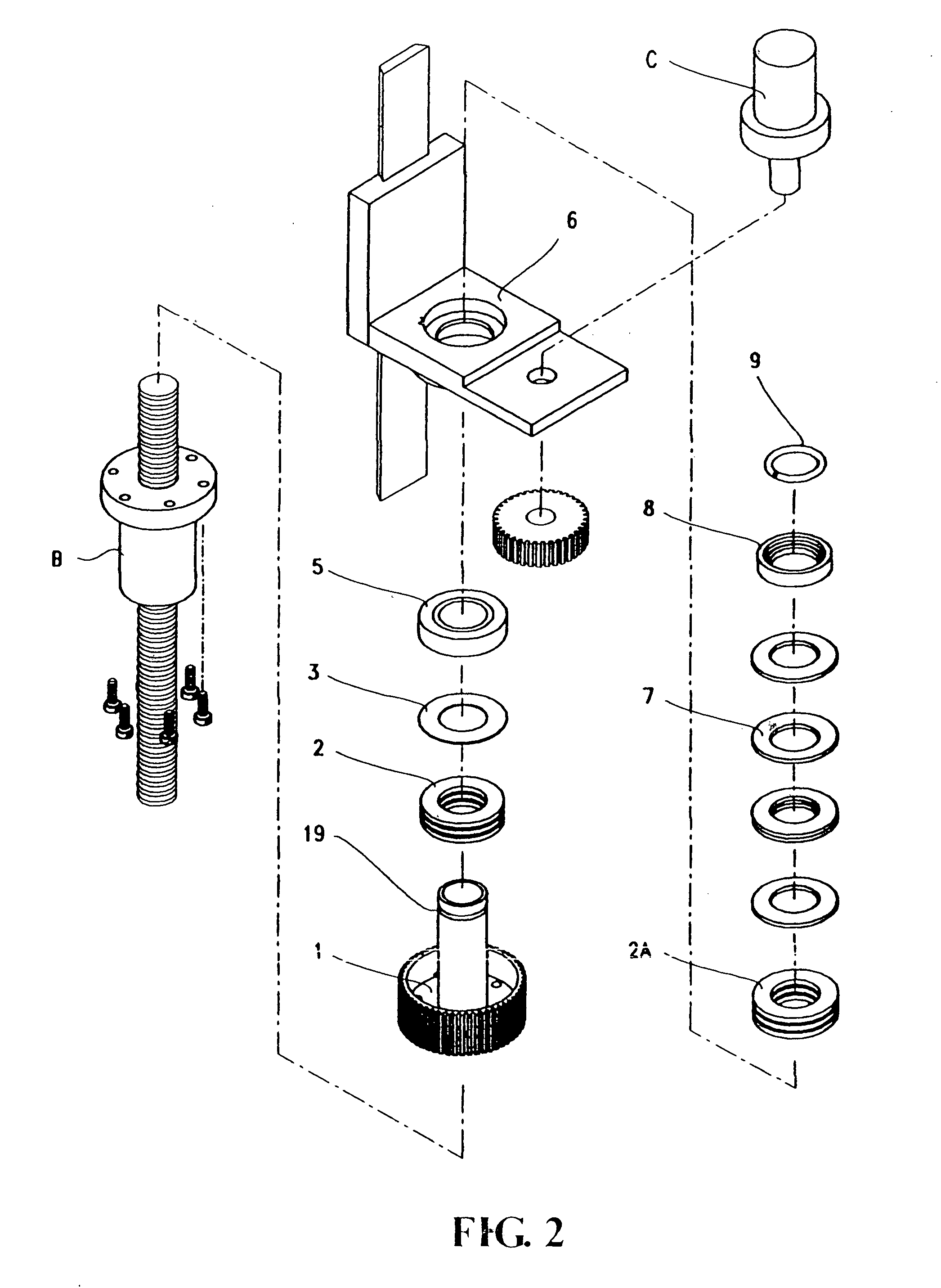
[0013] Please refer from FIG. 1 to FIG. 5, the present invention is provided a new construction of transmission gear sleeve with retarding descent function, it consists of a transmission gear sleeve 1 with retarding descent function, pressure bearing 2, 2A, washer 3, bearing 5, sliding seat 6, conical spring plate 7, seat 8, and retainer ring 9: its transmission gear sleeve 1 is a extruding tube with a position holding retaining groove 19 at one end is for fitting of two plates type pressure bearing 2, washer 3, bearing 5, sliding 6, two plates type pressure bearing 2A, conical spring plate 7 facing each other, and a retaining groove seat 8 in series in position, for purpose of tighten fitting of C shape clip and retaining ring 9 in position of holding retaining groove 19, therefore the design of seat 8 inner diameter is exactly the same of retaining ring 9 outside diameter, then the reverse force of spring plate would hold retaining ring 9 free from falling, this the outstanding de...


PUM


Abstract

The present invention provide with a new construction of transmission gear sleeve with retarding descent function, with one end of transmission gear sleeve bolt to the ball sleeve transmission member, and its other end in series connecting with two plates type pressure bearing, washer, bearing, sliding seat, two plates type pressure bearing, facing conical spring plates, seat and retaining ring in assembly, its features are: The extruding outward force of two sets of facing conical spring in transmission gear sleeve apply on two plates type pressure bearing, cause the tighten of transmission gear sleeve with sliding seat revolution by increasing of ball friction coefficient, then slow down the instant descending speed of sliding seat within safety range in case of system power cut.

Description

BACKGROUND OF THE INVETION [0001] (a) Technical Field of the Invention [0002] The invention relates to the new construction of transmission gear sleeve with retarded descent function during power cut of the system, a couple of facing conical spring plates on transmission gear sleeve extruding outward in order to press the two plates type pressure bearing, and then increasing the friction coefficient of the inner ball, therefore forcing the transmission gear sleeve to the sliding seat revolution tightly, and retarding the instant descending speed of the sliding seat favors the owner in case of a power cut [0003] (b) Description of the Prior Art [0004] The usually design of a vertical worm driving platform integrate the worm drive with the transmission bushing of sliding seat equipment, the upper and down displacement of platform is driven by the motor on side of the sliding seat, however, owing to the design of transmission bushing with sliding seat adapt bearing set, once system pow...

Claims


Application Information

Patent Timeline
Patent Type & Authority Applications(United States)
IPC IPC(8): F16H27/02
CPCB66F7/14Y10T74/18704F16H25/2454B66F17/00
Inventor WU, CHING-CHE
Owner WU CHING CHE
Why Eureka
Try Eureka