System for monitoring animal feed consumption

a feed consumption monitoring and system technology, applied in the field of animal feed consumption monitoring, can solve the problems of difficult measurement of feed conversion efficiency of individual animals within a co-fed group under traditional feedlot conditions, and existing systems that have not been designed to operate autonomously with high reliability, and have not provided for feed protection

Inactive Publication Date: 2007-06-21
TRAVIS BRYAN R
View PDF6 Cites 61 Cited by
  • Summary
  • Abstract
  • Description
  • Claims
  • Application Information

AI Technical Summary

Benefits of technology

[0008] In accordance with more specific aspects of the invention, a solar panel is employed to provide operating power for the electronic components of the system thereby eliminating the need of connecting the system to a power source. The enclosure provides protection for the electronic components from adverse environmental conditions including adverse weather conditions and spurious electrical currents. The identity of each animal entering the portal of the enclosure is determined by reading an RFID tag secured to the animal. The electronic components store data relating to all of the animals monitored by the system for an extended period of time thereby eliminating the necessity of coupling the electronic components to external computing and data storage facilities as is the case with prior art systems.

Problems solved by technology

Feed conversion efficiency of individual animals within a co-fed group under traditional feedlot conditions is difficult to measure due to the inherent difficulty of determining how much feed each animal has eaten from a communal feed trough.
However, existing systems have not been designed to operate autonomously with high reliability in remote areas, nor have they provided for protection of feed from environmental elements.
As a result, cattle breeders seeking to measure and apply feed conversion efficiency as a selection criteria for breeding have heretofore been unable to apply existing systems to feeding environments comprising the harsh conditions experienced at remote outdoor locations such as pastures, feedlots, etc.

Method used


Image

  • System for monitoring animal feed consumption
  • System for monitoring animal feed consumption
  • System for monitoring animal feed consumption

Examples


first embodiment

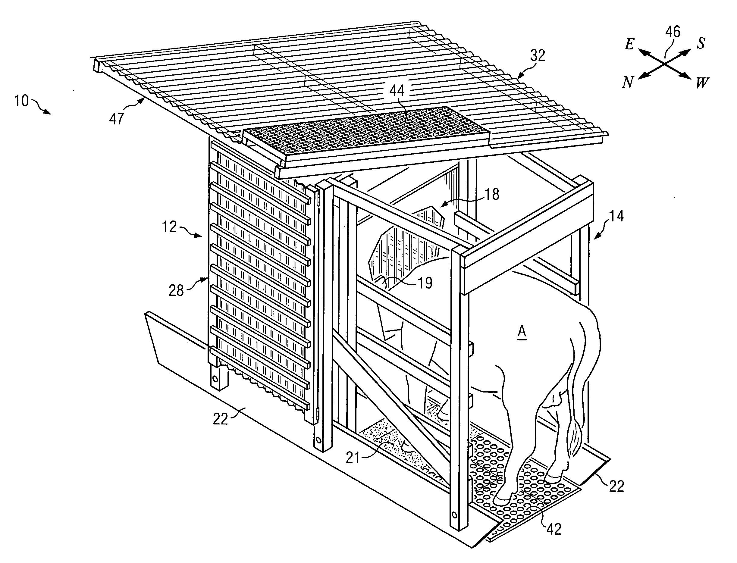
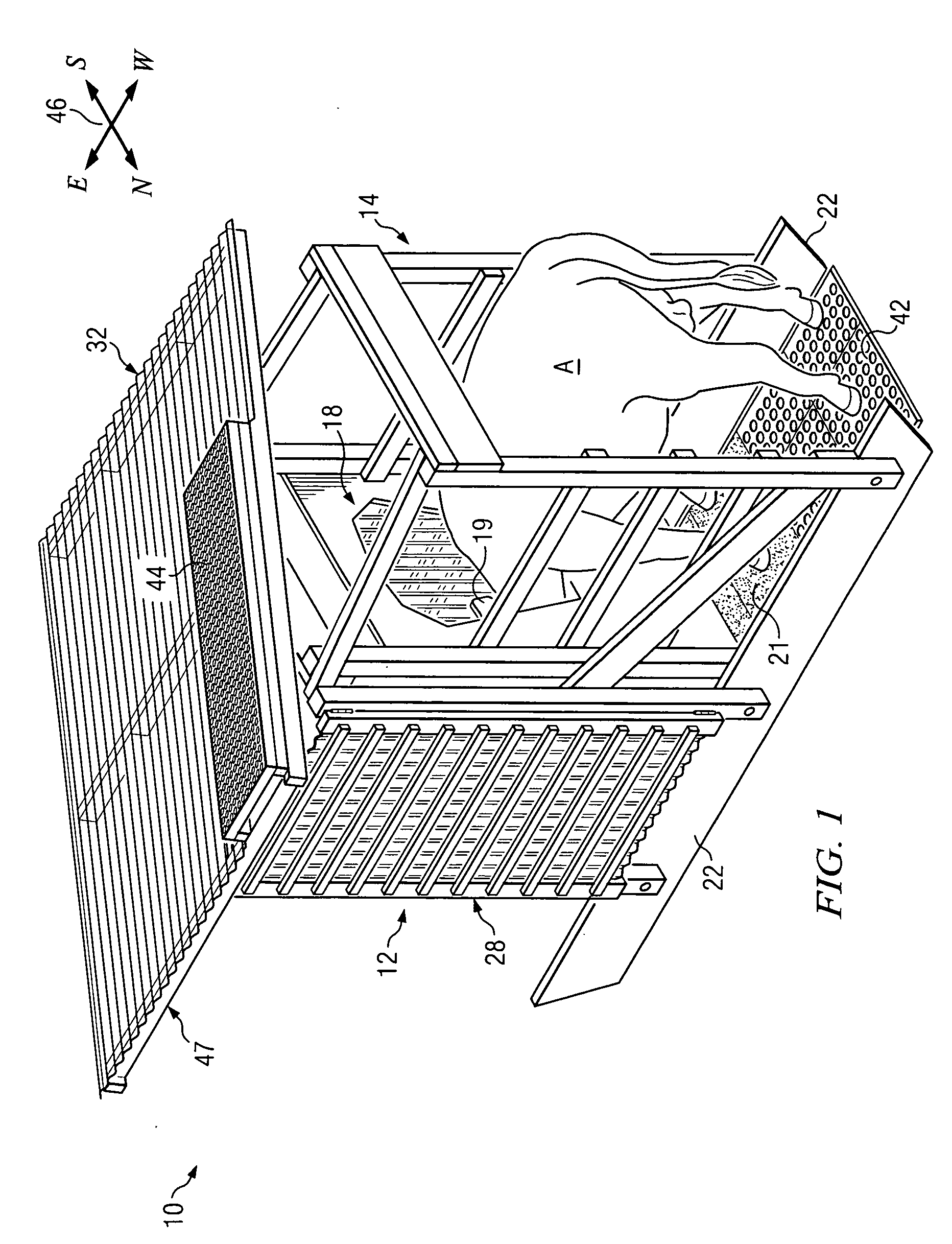
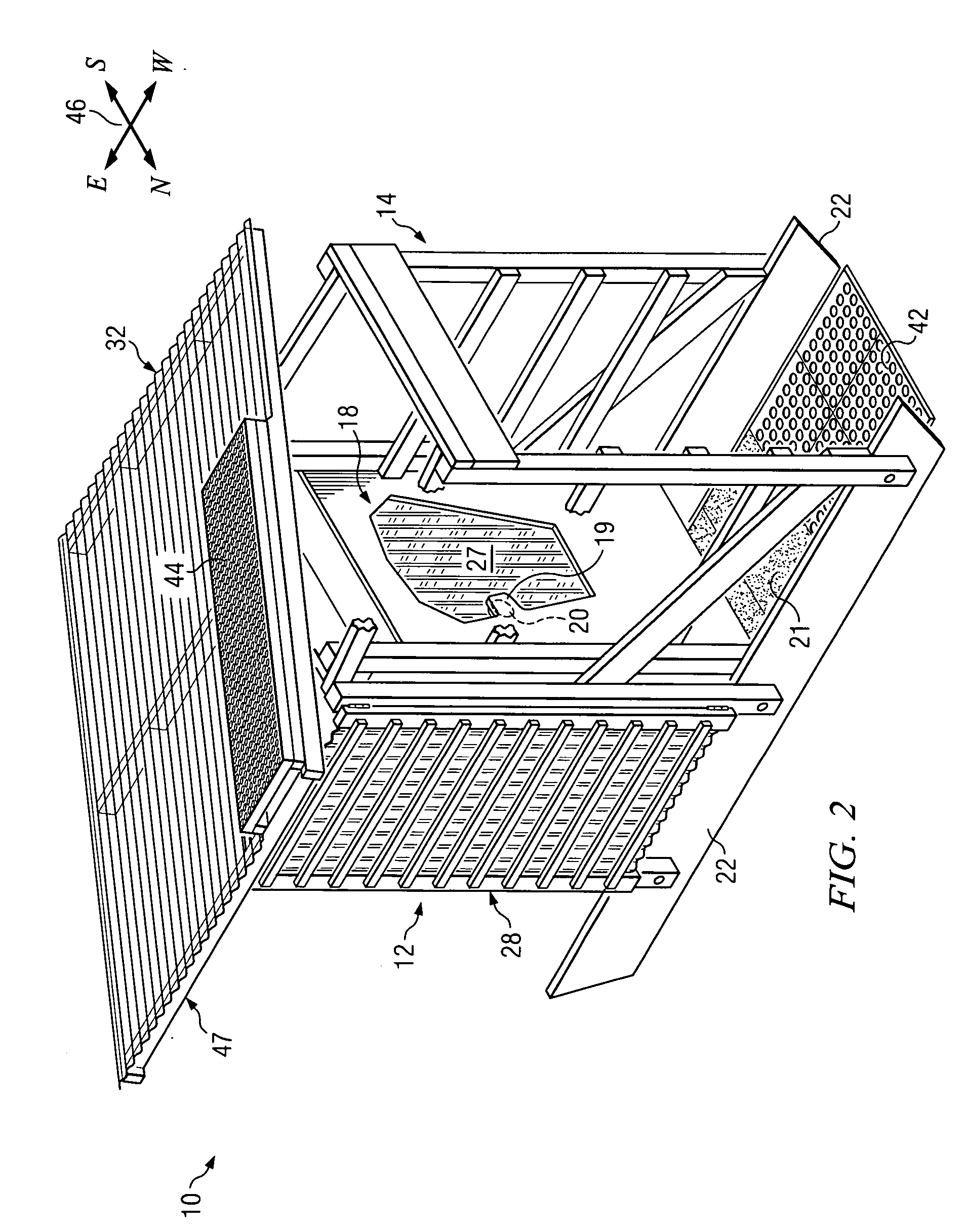
[0018] Referring now to the Drawings, and particularly to FIGS. 1, 2, 3, and 4 thereof, there is shown a system for monitoring animal feed consumption 10 comprising the present invention. The system comprises an enclosure 12, a stall 14, and a portal 18 located between the enclosure 12 and the stall 14. The stall 14 can be a separate structure normally secured to the enclosure 12 and detachable therefrom for transport, etc. The stall 14 and the portal 18 can also be attached to or located inside of a pre-existing outdoor enclosure or barn. Alternatively, the portal 18 can be deployed separately as a stand alone device in appropriate circumstances.

[0019] In and of itself the portal 18 comprises an important feature of the invention. The portal 18 includes an intrusion 19 having an RFID antenna 20 secured to the inside surface thereof. The specific shape and placement of the intrusion 19 is such that an RFID tag secured to the ear of an animal utilizing the system 10 passes by the ant...

second embodiment

[0035] Referring to FIG. 7 there is shown a system for monitoring animal feed consumption 80 comprising the present invention. Many of the component parts of the feed monitoring system 80 are substantially identical in construction and function to component parts of the feed monitoring system 10 illustrated in FIGS. 1 through 6, inclusive, and described hereinabove in conjunction therewith. Such identical component parts are designated in FIG. 7 with the same reference numerals utilized above in the description of the feed monitoring system 10 but are differentiated therefrom by means of a prime (′) designation.

[0036] The feed monitoring system 80 differs from the feed monitoring system 10 in that the feed monitoring system 80 comprises two feed bins 36′ within an enclosure 12′. Accordingly, the enclosure 12′ comprises a second access portal 18′ with its own RFID antenna installed thereon and a second stall 14′ having a second sensor 40′ therein. The enclosure 12′ further comprises ...

third embodiment

[0037] Referring to FIG. 8 there is shown a feed monitoring system 82 comprising the present invention. Many of the component parts of the feed monitoring system 82 are substantially identical in construction and function to component parts of the feed monitoring system 10 illustrated in FIGS. 1 through 6 and described hereinabove in conjunction therewith. Such identical component parts are designated in FIG. 8 with the same reference numerals utilized above in the description of the feed monitoring system 10 but are differentiated therefrom by means of a double prime (″) designation.

[0038] The feed monitoring system 82 differs from the feed monitoring system 10 in that the feed monitoring system 82 comprises four feed bins 36″ within an enclosure 12″. Accordingly, the enclosure 12″ comprises four access portals 18″, each with its own RFID antenna installed thereon. Each access portal 18″ has a stall 14″ adjacent thereto with a sensor 40″ installed in each stall 14″. The enclosure 1...


PUM


Abstract

An automated animal feed consumption monitoring system comprises an enclosure having a quantity of feed therein. A sensor detects an animal's entry into a stall adjacent the enclosure and activates the system to record the entry time and entry weight of the feed. An RFID reader, by means of an RFID antenna located along the path of movement of the animal's RFID tag, identifies the specific animal that has entered the stall to feed. When the animal leaves the stall, the exit time and exit weight of the feed are recorded.

Description

CLAIM OF PRIORITY [0001] Applicant claims priority based on provisional patent application Ser. No. 60 / 751,143 filed Dec. 16, 2005, the entire content of which is incorporated herein by reference.TECHNICAL FIELD [0002] This invention relates generally to animal feed consumption monitoring, and more particularly to a stand alone, autonomous, self-contained feeding station for monitoring animal feed consumption at other outdoor locations such as pastures, feedlots, etc. BACKGROUND AND SUMMARY OF THE INVENTION [0003] Investors in cattle destined for feedlots place higher value on animals that are more efficient at converting feed into beef under feedlot conditions. An animal exhibits higher feed conversion efficiency when it consumes less dry feed per unit of weight gained as compared with other animals under the same conditions. Feedlot operators typically bill cattle investors for the feed, medicines, and other services consumed by the investors' cattle during their conditioning for ...

Claims


Application Information

Patent Timeline
Patent Type & Authority Applications(United States)
IPC IPC(8): A01K5/02
CPCA01K5/02A01K5/0283
Inventor TRAVIS, BRYAN R.
Owner TRAVIS BRYAN R
Why Eureka
Try Eureka