
Processing apparatus

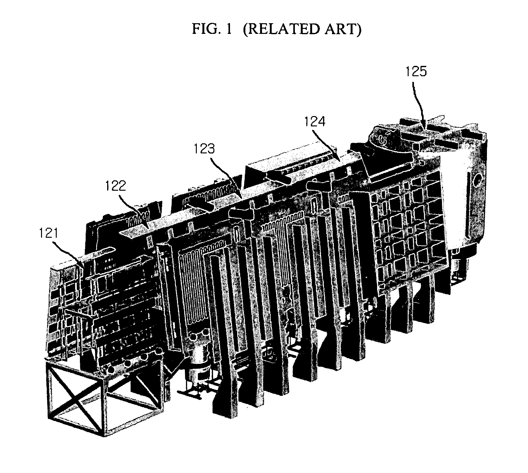
a processing apparatus and lcd technology, applied in the direction of vacuum evaporation coating, chemical vapor deposition coating, coating, etc., can solve the problems of increasing manufacturing cost, reducing product yield, and difficult replacement and maintenance of carriers, so as to reduce processing time, improve product yield, and reduce tact time

Active Publication Date: 2007-06-21
LG DISPLAY CO LTD +2
View PDF4 Cites 16 Cited by
  • Summary
  • Abstract
  • Description
  • Claims
  • Application Information

AI Technical Summary

Benefits of technology

[0019] An object of the present invention is to provide a processing apparatus that improves a product yield.
[0020] Another object of the present invention is to provide a processing apparatus that reduces a processing time.
[0021] Another object of the present invention is to provide a processing apparatus that reduces a tact time.
[0022] Another object of the present invention is to provide a processing apparatus that reduces a device volume and manufacturing cost without using a carrier.
[0023] Another object of the present invention is to provide a processing apparatus that reduces a manufacturing cost.

Problems solved by technology

Accordingly, the size of components and the volume of the chamber in the cluster-type processing apparatus increases, thereby increasing the manufacturing cost.
Hence, processing time increases, thus decreasing product yield.
Replacement and maintenance of carriers are difficult.
Hence, device cost increases with each additional carrier.

Method used


Image

  • Processing apparatus
  • Processing apparatus
  • Processing apparatus

Examples


Embodiment Construction

[0038] Reference will now be made in detail to exemplary embodiments of the present invention, which are illustrated in the accompanying drawings.

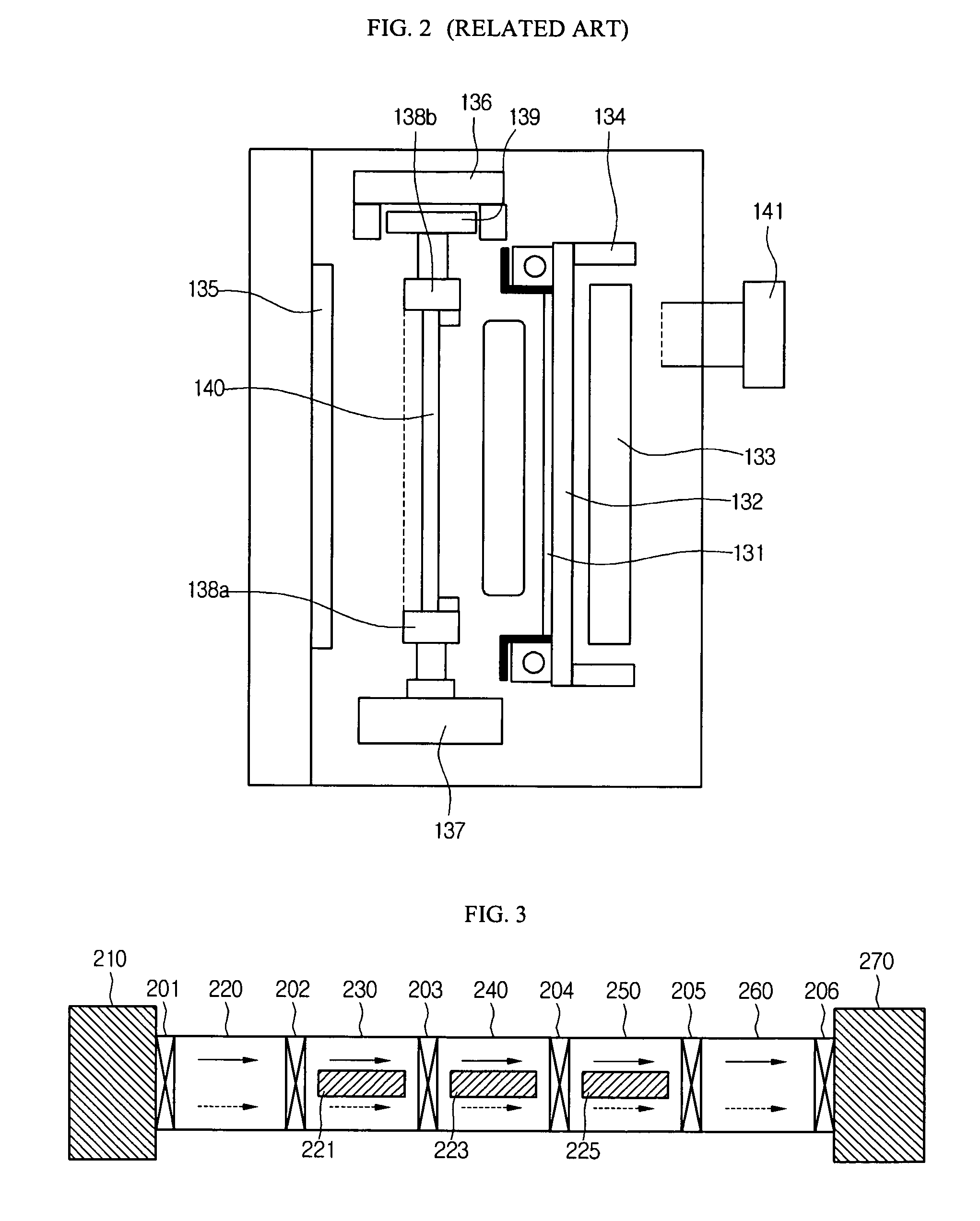
[0039]FIG. 3 is a plan view of a first exemplary in-line processing apparatus according to a first embodiment of the present invention. Referring to FIG. 3, an in-line processing apparatus includes a first conveying unit 210, a loading chamber 220, a buffer chamber 230, a first process chamber 240, a second process chamber 250, an unloading chamber 260, and a second conveying unit 270. Gate valves 201, 202, 203, 204, 205 and 206 may be disposed to control a substrate transfer between the first and second conveying units 210 to 270.

[0040] The substrate to be processed is placed on the first conveying unit 210. Then, the substrate to be processed is loaded on the loading chamber 220. The buffer chamber 230 temporarily buffers the substrate transferred from the loading chamber 220. The buffering process includes pre-setting vacuum and tempe...


PUM

PropertyMeasurementUnit
temperatureaaaaaaaaaa
distanceaaaaaaaaaa
sizeaaaaaaaaaa

Abstract

A processing apparatus includes a loading chamber; a buffer chamber connected to the loading chamber; a first process chamber connected to the buffer chamber; and an unloading chamber connected to the first process chamber, wherein a processing path through the processing apparatus is a forward in-line path in a direction through the loading chamber, the buffer chamber, the first process chamber, and the unloading chamber.

Description

[0001] This application claims the benefit of Korean Patent Application No. 2005-0124311, filed on Dec. 16, 2005, which is hereby incorporated by reference in its entirety. BACKGROUND OF THE INVENTION [0002] 1. Field of the Invention [0003] Embodiments of the present invention relate to a processing apparatus, and more particularly, to a processing apparatus for an LCD device. Embodiments of the present invention are suitable for a wide scope of applications. In particular, an embodiment of the present invention is suitable for providing a processing apparatus capable of improving a manufacturing process efficiency. [0004] 2. Description of the Related Art [0005] Generally, semiconductor devices and display panels, such as liquid crystal display devices and organic light emitting display devices, are fabricated in a processing apparatus. The processing apparatus performs repeated manufacturing processes required for processing a wafer for a semiconductor device or a substrate for a ...

Claims


Application Information

Patent Timeline
Patent Type & Authority Applications(United States)
IPC IPC(8): C23F1/00C23C16/00
CPCC23C14/50C23C14/568H01L21/67173
Inventor LEE, JIN SEOKYOON, HYUK SANGYOO, HWAN KYUHWANG, BYEONG EOK
Owner LG DISPLAY CO LTD
Learn More