

Rotary valve for handling solid particulate material
a technology of solid particulate material and rotary valve, which is applied in the direction of movable measuring chambers, instruments, volume meters, etc., can solve the problems of deformation of the seal of the rotary valve, affecting the sealing effect, and causing wear and tear, so as to improve the sealing arrangement
- Summary
- Abstract
- Description
- Claims
- Application Information
AI Technical Summary
Benefits of technology
Problems solved by technology
Method used
Image

Examples
Embodiment Construction
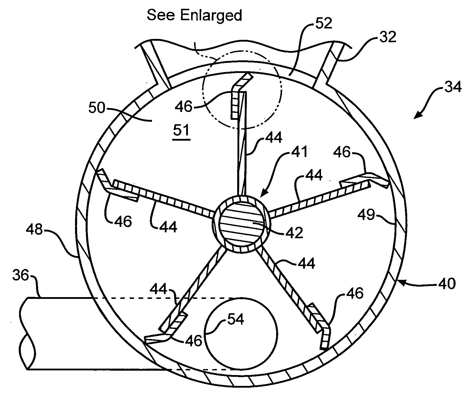
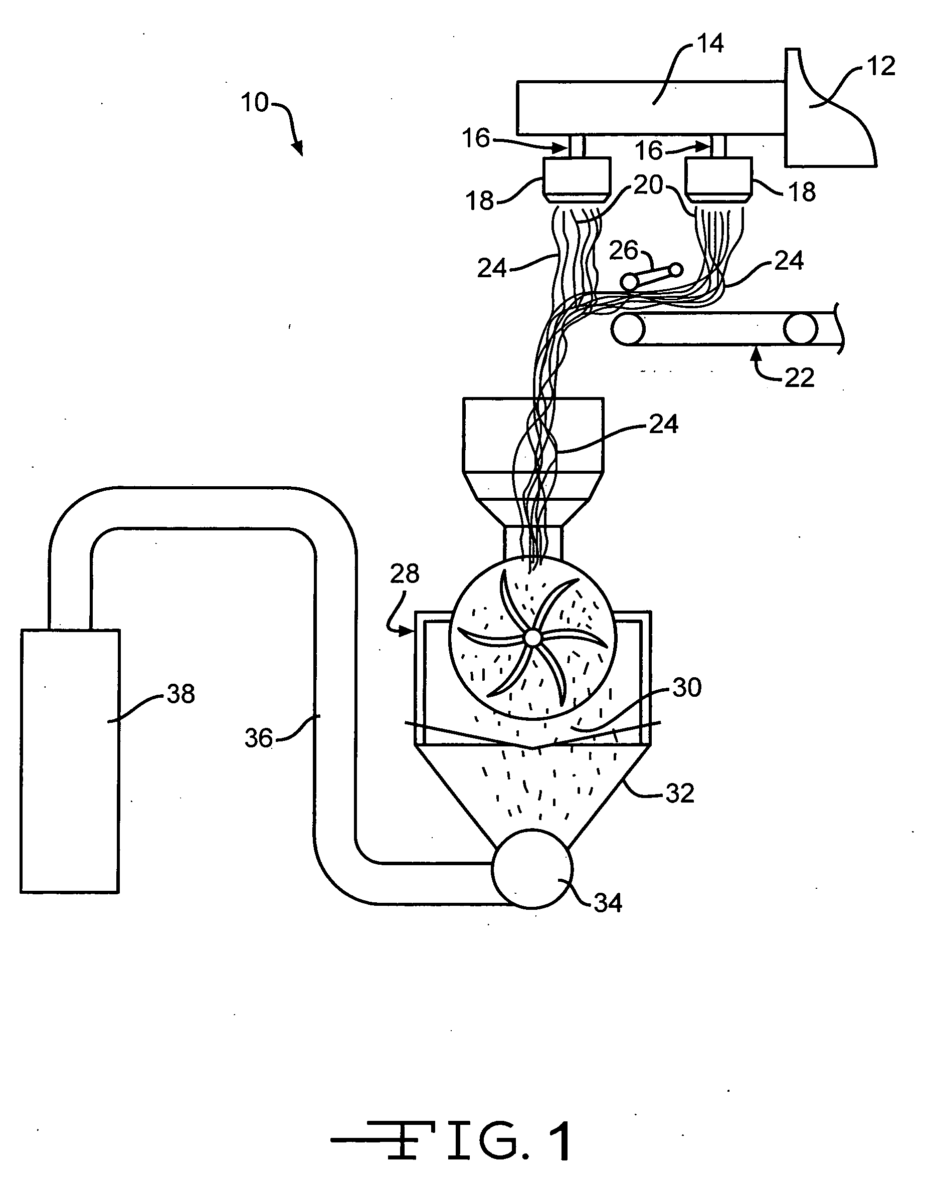
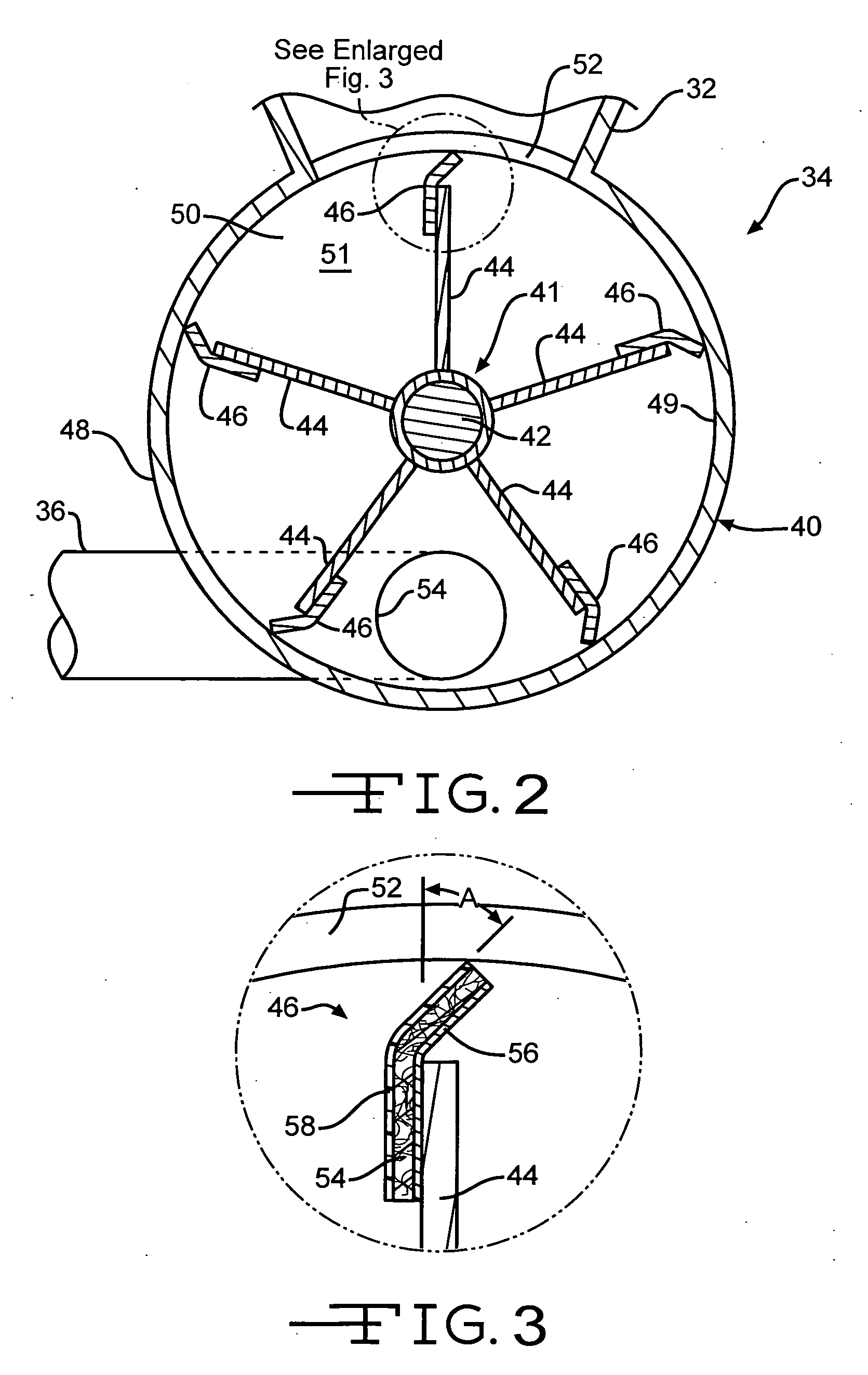
[0023] Although specific terms are used in the following description for the sake of clarity, these terms are intended to refer generally to the structures of the invention selected for illustration in the Figures, and are not intended to define or limit the scope of the invention. Referring now to the drawings, there is illustrated in FIG. 1 a system 10 for production of loose fill fiberglass insulation. It must be noted that while particular embodiments of the present invention will be described in an environment related to the production of loose fill fiberglass insulation, the present invention is not to be limited to such an environment. It must be understood that the invention may be practiced with any fibrous insulation material, such as any compressible fibrous material made of mineral fibers or polymeric fibers or both.
[0024] As can be seen in FIG. 1, streams 16 of molten glass are supplied from a forehearth 14 of a furnace 12 to rotary fiberizers 18 to form veils 20 of gl...
PUM
 Abstract
Description
Claims
Application Information