Communication terminal and communication method

a technology of communication terminal and communication method, applied in the field of communication terminal, can solve the problem that smooth processing cannot be achieved between

Inactive Publication Date: 2007-06-21
PANASONIC CORP
View PDF3 Cites 36 Cited by
  • Summary
  • Abstract
  • Description
  • Claims
  • Application Information

AI Technical Summary

Benefits of technology

[0010] According to the invention, the data to execute the function that the home terminal installs and the data to execute the function that the associated communication terminal installs are generated, whereby if the t

Problems solved by technology

However, in the video telephone in the related art, all video telephones have not necessarily the same processing capability and when communications are conducted between the video telephones different in processing capability,

Method used


Image

  • Communication terminal and communication method
  • Communication terminal and communication method
  • Communication terminal and communication method

Examples


first embodiment

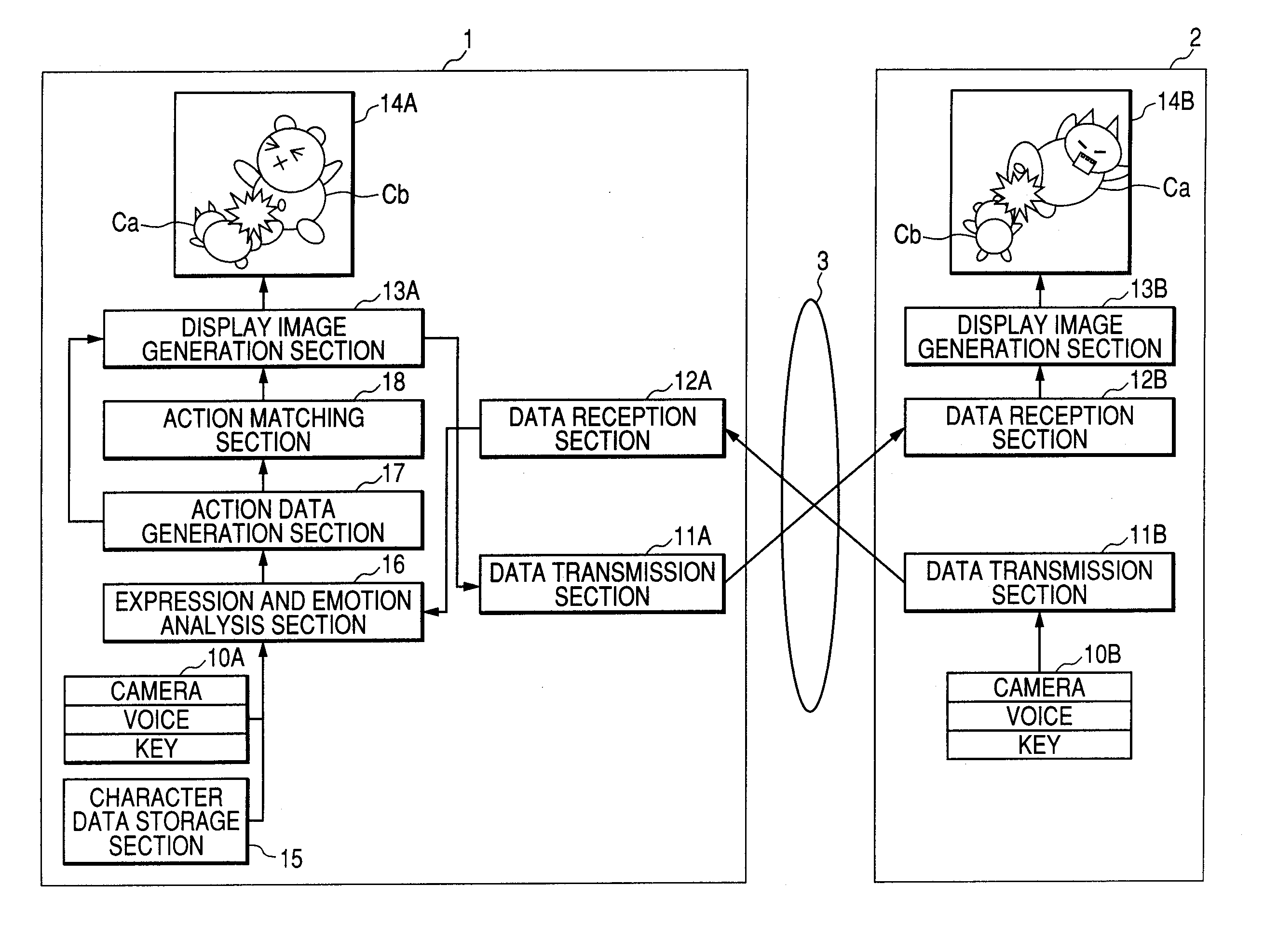
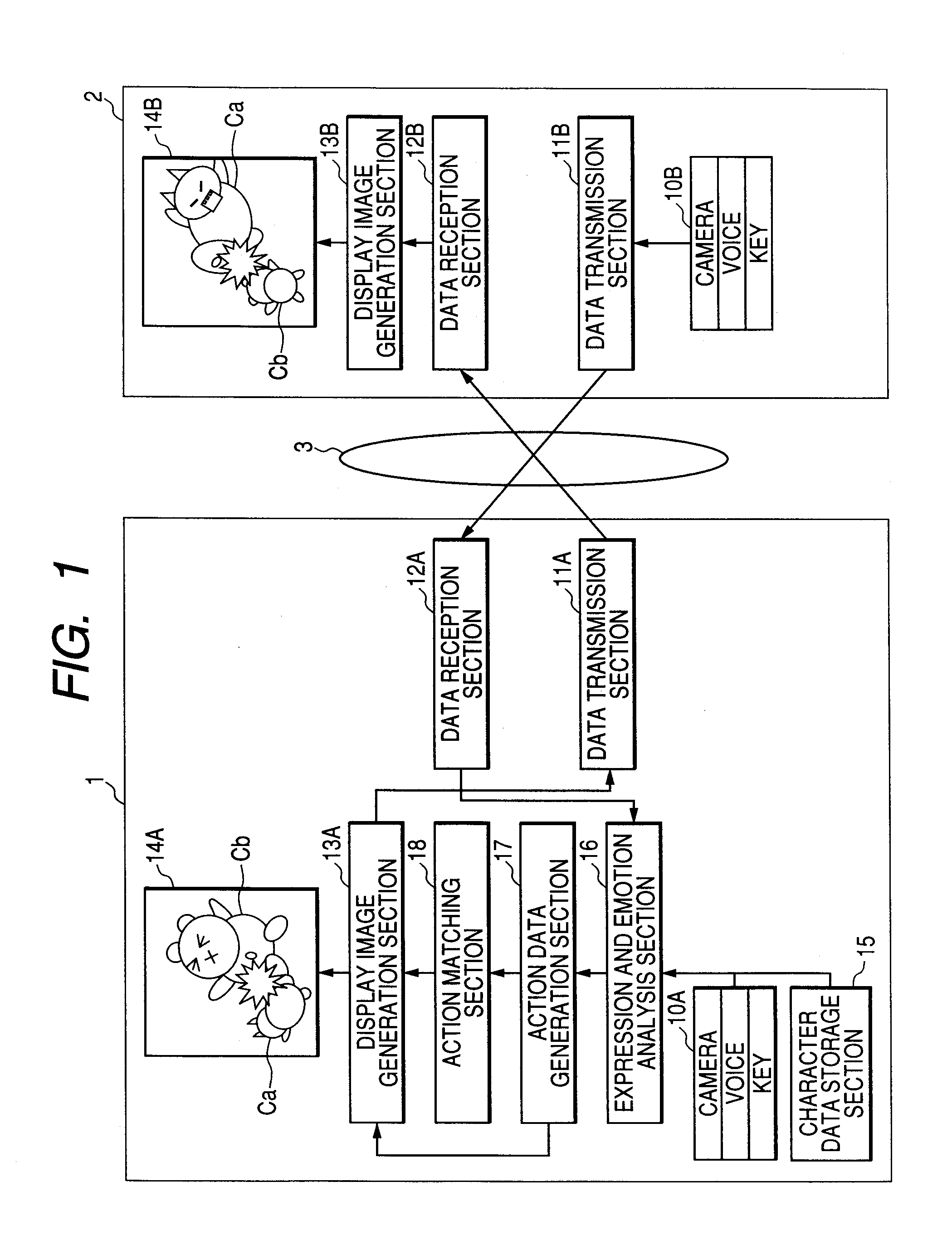
[0047]FIG. 1 is a schematic configuration diagram of a video telephone system to describe a first embodiment of the invention. The video telephone system shown in FIG. 1 includes video telephones 1 and 2 which have a communication function, install a common function to a function that an associated communication terminal installs, and differ in terminal capability, and enables them to communicate with each other through a network 3. For example, IP (Internet Protocol) is used for communications between the video telephones 1 and 2. In the embodiment, the case where the terminal capability of the video telephone 1 is higher than that of the video telephone 2 will be discussed. It is assumed that the video telephone 1 has a function of generating a character used common to the video telephone 2 (character used as user's alter ego called avatar) and a character is displayed instead of the facial image of the image during the conversation with the video telephone 2. In the description t...

second embodiment

[0098]FIG. 11 is a schematic configuration diagram of a video telephone system to describe a second embodiment of the invention. The video telephone system shown in FIG. 11 includes video telephones 4 and 5 which have a communication function, install a common function to a function that an associated communication terminal installs, and have the same degree of terminal capability. Parts common to those in FIG. 1 are denoted by the same reference numerals in FIG. 11 and the video telephones include each a character data storage section, an expression and emotion analysis section, an action data generation section, and an action matching section and therefore “A” is added to the sections of the video telephone 4 and “B” is added to the sections of the video telephone 5. The video telephones 4 and 5 exchange character data at the telephone conversation start time and thus have character data retention sections 19A and 19B for retaining the character data of the associated party.

[0099...

third embodiment

[0111]FIG. 16 is a schematic configuration diagram of a video telephone system to describe a third embodiment of the invention. The video telephone system shown in FIG. 16 includes video telephones 6 and 7 which have a communication function, install a common function to a function that an associated communication terminal installs, and have the same degree of terminal capability. Parts common to those in FIG. 1 are denoted by the same reference numerals in FIG. 16 and further the video telephone 6 includes an image process data storage section 20 in place of the character data storage section 15, an image process determination section 21 in place of the action data generation section 17, and an action process matching section 22 in place of the action matching section 18 and therefore “A” is added to the sections of the video telephone 6 and “B” is added to the sections of the video telephone 7.

[0112] In the embodiment, the display image and the transmission image to be created ar...


PUM


Abstract

An object of the invention is to provide a communication terminal capable of causing an associated communication terminal to execute the function at the level required by the home terminal.
A communication terminal of the invention is a video telephone 1 having a communication function and installing a common function to a function that a video telephone 2 installs, and includes a display image generation section 13A for generating data to execute the function that the video telephone 1 installs and data to execute the function that the video telephone 2 installs, and a data transmission section 11A for transmitting the data to execute the function that the video telephone 2 installs.

Description

TECHNICAL FIELD [0001] This invention relates to a communication terminal having a communication function and installing a common function to a function that an associated communication terminal installs and a communication method of the communication terminal. BACKGROUND ART [0002] Hitherto, a video telephone provided with a function of sending a character called avatar to an associated communication terminal instead of a photograph image of the user has been developed (for example, refer to patent document 1). [0003] Patent document 1: JP-A-003-109036 (page 3, page 4, FIG. 2) DISCLOSURE OF THE INVENTION PROBLEMS THAT THE INVENTION IS TO SOLVE [0004] However, in the video telephone in the related art, all video telephones have not necessarily the same processing capability and when communications are conducted between the video telephones different in processing capability, communications are conducted in accordance with the processing capability of the video telephone having the l...

Claims


Application Information

Patent Timeline
IPC IPC(8): H04N7/14G06F3/01G06T15/70H04B7/26H04M11/00H04M11/08H04W4/00H04W8/22
CPCG06F3/011H04M11/085H04N7/147
Inventor HADA, TETSUMATSUO, HIDEAKINOGOSHI, HIROKISUZUKI, NAOYUKIMAKINO, TAKAHIRO
Owner PANASONIC CORP
Why Eureka
Try Eureka