Electronic device and function assigning method

a technology of electronic devices and functions, applied in the field of electronic devices, can solve the problems of difficult user-remembering functions, inability to quickly operate video cameras, and troublesome operation,

Inactive Publication Date: 2007-06-21
SONY CORP
View PDF12 Cites 7 Cited by
  • Summary
  • Abstract
  • Description
  • Claims
  • Application Information

AI Technical Summary

Benefits of technology

[0006] Therefore, an object of the present invention is to provide an electronic device and a method of assigning functions that allow a function of quickly displaying a setting screen for menu items or a setting screen for non-menu items to be assigned to a key so as to improve the operability of the electronic device.
[0007] To solve the foregoing problem, the present invention is an electronic device having a display panel and a plurality of keys to which desired functions can be assigned, comprising:

Problems solved by technology

Thus, the video camera cannot be quickly operated and there are not a lot of changes that user sees these functions.
Consequently, its operation would become bothersome.
In addition, it is difficult for the user to remember functions that he or she has assigned to the key.
Thus, it cannot be said that the operability is improved with the technology.
In addition, since functions are not assigned to a plurality of keys, it cannot be said that the operability of the method of assigning functions is satisfactory.

Method used


Image

  • Electronic device and function assigning method
  • Electronic device and function assigning method
  • Electronic device and function assigning method

Examples


Embodiment Construction

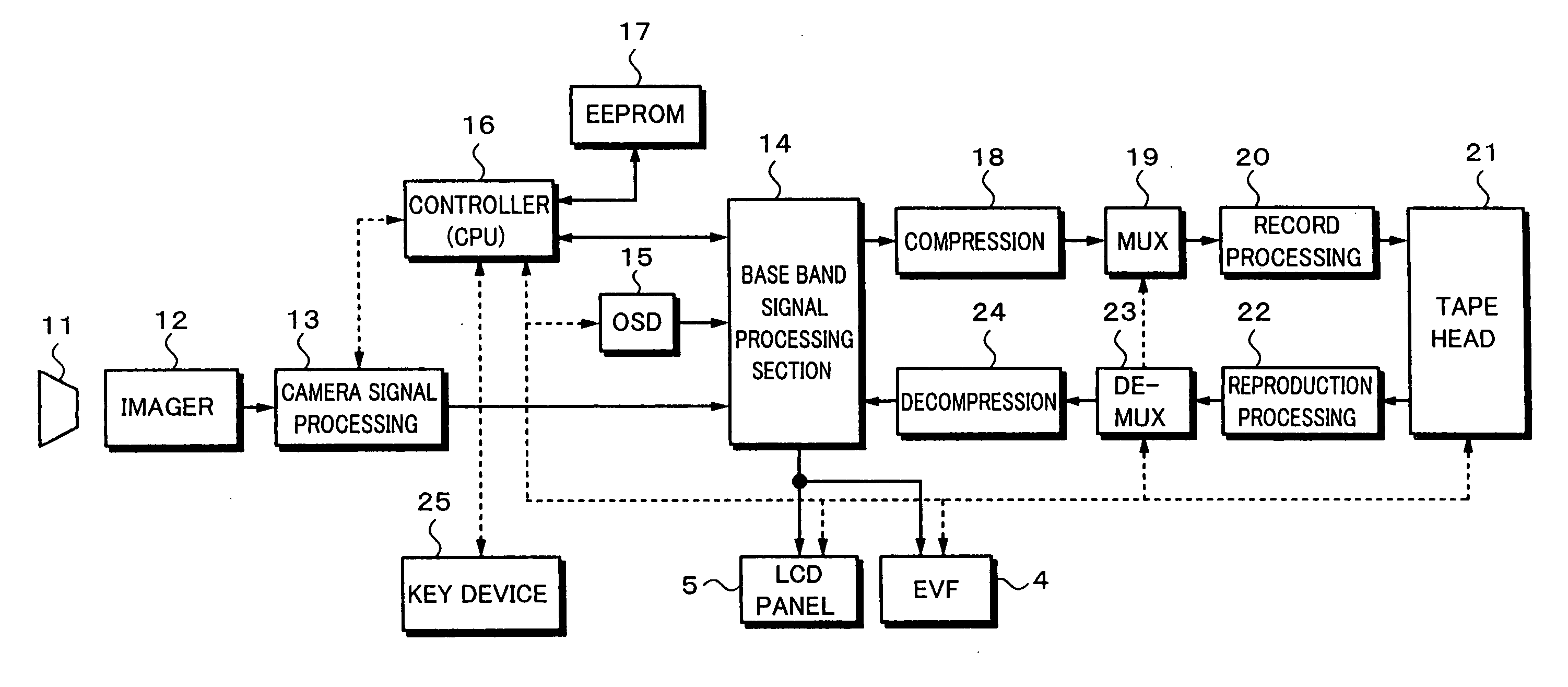
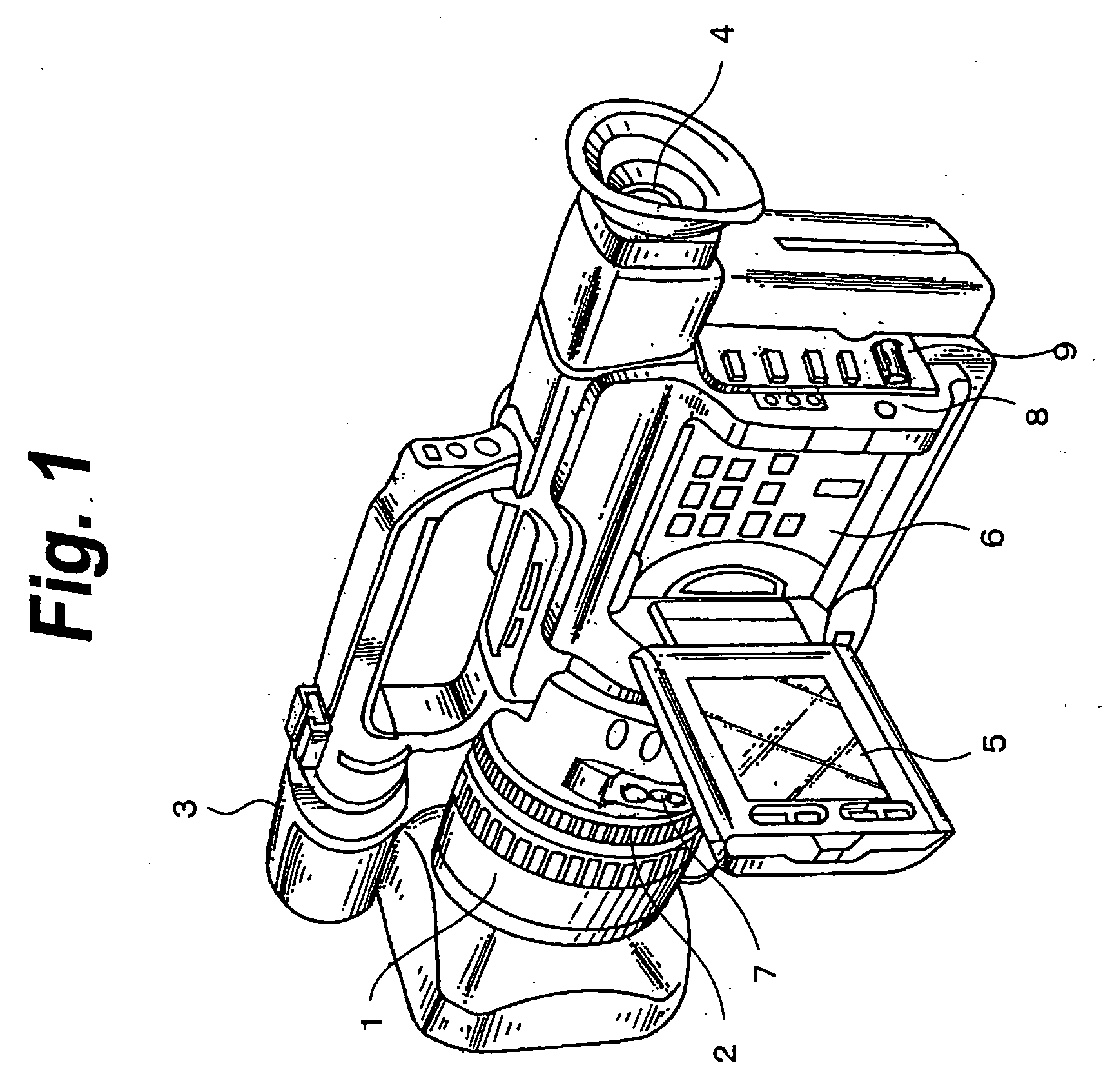
[0021] Next, with reference to the accompanying drawings, an embodiment of the present invention will be described. FIG. 1 shows an external structure of a video camera according to the present invention. Reference numeral 1 denotes a lens housing section. Light from an object enters an imager such as a CCD through a lens. Reference numeral 2 denotes a zoom ring. Reference numeral 3 denotes a stereo microphone. Reference numeral 4 denotes an electronic view finder.

[0022] Reference numeral 5 denotes a liquid crystal display monitor of for example 2.5 inch type. The liquid crystal display monitor 5 can be freely housed in a concave housing portion 6 on one side of the body. A tape cassette housing section (not shown) is disposed on the other side of the body. The tape cassette housing section houses for example a DV (Digital Video) standard tape cassette. An object is shot by a camera section. The resultant video signal of the object is processed. The processed video signal is record...


PUM


Abstract

At step ST2, an assign key changing item is selected from menu items. At step ST3, an assign key to which a function is assigned is selected. At step ST4, a function to be assigned is selected. The selected function is assigned to the selected assign key. At step ST5, a setting result indication screen appears. When one of two paired functions is assigned, a message which prompts a user to assign the other function. After the message has appeared for a predetermined time, the latest assigned states appear. At step ST6, the latest assign key information is stored to a non-volatile memory. To quit an assigning process, a menu button 8 is pressed and the menu is closed (at step ST8).

Description

TECHNICAL FIELD [0001] The present invention relates to an electronic device, such as a video camera, a digital camera, a cellular phone, or a PDA, which has a display panel and an operating section and also to a method of assigning a function to a key. BACKGROUND ART [0002] As an electronic device such as a video camera is becoming small, the number of hard keys (hereinafter simply referred to as keys) tends to decrease. As a result, functions that cannot be assigned to keys need to be operated on a menu. Thus, the video camera cannot be quickly operated and there are not a lot of changes that user sees these functions. Consequently, its operation would become bothersome. [0003] Even if many keys are provided, since the purpose for which the user uses the video camera depends on himself or herself, all functions pre-assigned to keys are not always functions that the user needs with keys. [0004] In contrast with related art of which only one function the user desires is assigned to ...

Claims


Application Information

Patent Timeline
Patent Type & Authority Applications(United States)
IPC IPC(8): H04N5/76G06F3/02G06F3/00G06F3/023H03M11/04H04N5/225H04N5/232
CPCH04N5/23293G06F3/0238H04N23/631G06F3/02H03M11/04G06F3/00H04N23/00H04N23/617H04N23/62
Inventor OHASHI, HISASHI
Owner SONY CORP
Why Eureka
Try Eureka