Multifunction dual lens matching device for stereoscopic 3D camera system

Inactive Publication Date: 2007-06-21
3ALITY DIGITAL SYST
View PDF4 Cites 11 Cited by
  • Summary
  • Abstract
  • Description
  • Claims
  • Application Information

AI Technical Summary

Benefits of technology

[0011] To control two lenses in a 3D camera rig such that they match as closely as possible in “actual” position, a new error variable is calculated, based on the dif

Problems solved by technology

While this works just fine in a regular 2D camera system to control the lens positions, namely Focus, Iris, and Zoom (and sometimes Back-Focus), th

Method used


Image

  • Multifunction dual lens matching device for stereoscopic 3D camera system
  • Multifunction dual lens matching device for stereoscopic 3D camera system
  • Multifunction dual lens matching device for stereoscopic 3D camera system

Examples


Embodiment Construction

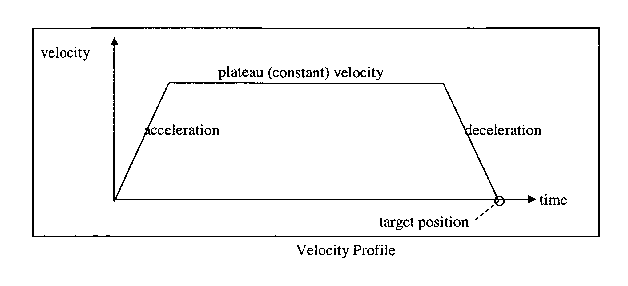
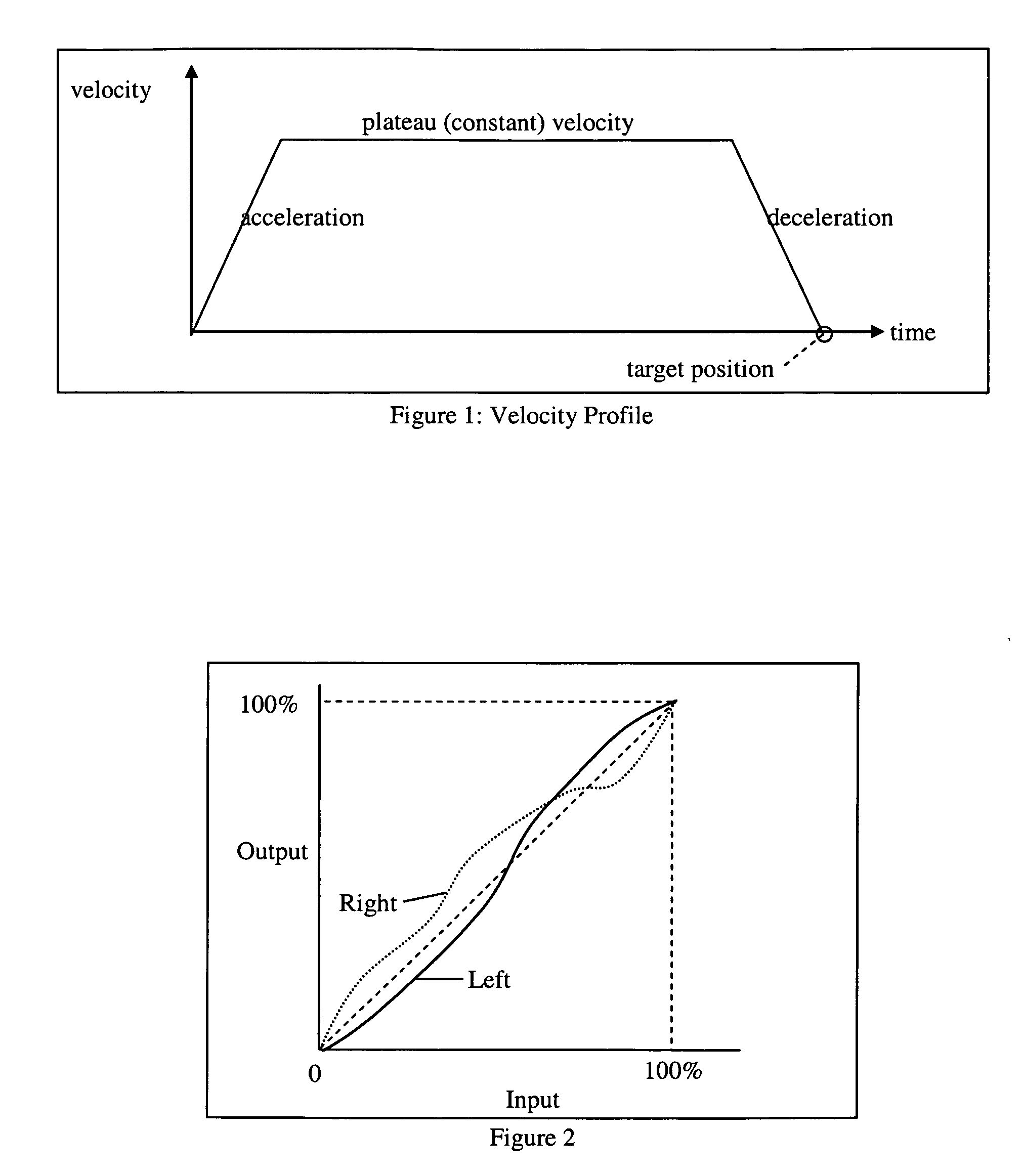
[0017] The PID3D Algorithm_will drive a pair of motors to match each other, using the difference error and a new difference gain coefficient, such that the difference will generate a force to each motor to drive the motors towards each other. The difference gain coefficient needs to be sufficiently large to overcome the torque differences between both motors. The PID3D algorithm can not be implemented in a motion control co-processor, such as the National LM629 chip, commonly used by the entertainment industry for motion control. The PID processing is an internal function of these chips, and is not accessible by the outside world. We started from scratch and coded our own high performance processor to perform the PID3D algorithm which runs at 75 MIPS (million instructions per second), which includes the PID3D algorithm, trajectory generation, velocity profiling, quadrature position feedback, quadrature noise filtering, target remapping (described below), ultrasonic PWM drive, serial...


PUM


Abstract

This invention is for target remapping, telecentricity compensation, and a new PID motion control algorithm to align and control to a very high tolerance multiple functions to two lenses simultaneously in a stereoscopic 3D camera system. To control two lenses in a 3D camera rig such that they match as closely as possible in “actual” positions, a new error variable is calculated, based on the difference between the “actual” positions of both lenses. This is added to the PID formula, as a new statement, with a new coefficient, which we call the PID3D algorithm.

Description

CROSS-REFERENCE TO RELATED APPLICATIONS [0001] This application claims priority to provisional application entitled, MULTIFUNCTION DUAL LENS MATCHING DEVICE FOR A STEREOSCOPIC 3D DIGITAL CAMERA SYSTEM, filed Jul. 14, 2005, having a Ser. No. 60 / 698,964, which is hereby incorporated by reference in its entirety.FIELD OF THE INVENTION [0002] The present invention relates generally to stereoscopic 3D camera systems, and more particularly to the lenses used by such cameras. BACKGROUND OF THE INVENTION [0003] Most implementations of motion control for a camera's lens system use a dedicated motion control chip (such as a National Semiconductor LM629). These chips behave as a co-processor in a multi-axis motion control system. They typically implement the common PID (Proportional, Integral, Derivative) algorithm for motion control, along with trajectory generation, velocity profiling, quadrature position feedback, and PWM circuits. [0004] While this works just fine in a regular 2D camera sy...

Claims


Application Information

Patent Timeline
IPC IPC(8): G03B17/00H04N13/239
CPCG03B35/08H04N13/0239H04N13/0296H04N13/296H04N13/239
Inventor BUTLER-SMITH, BERNARD J.SCHKLAIR, STEVEN J.
Owner 3ALITY DIGITAL SYST
Why Eureka
Try Eureka