

Gear milling tool with replaceable cutting inserts
a technology of inserts and gear milling tools, which is applied in the direction of gear teeth, manufacturing tools, gear-teeth manufacturing apparatus, etc., can solve the problems of time-consuming and costly sharpening of cutting blades, wear of one or more cutting blades, and cutting blades that require sharpening
- Summary
- Abstract
- Description
- Claims
- Application Information
AI Technical Summary
Benefits of technology
Problems solved by technology
Method used
Image

Examples
second embodiment
[0039] Turning now to FIGS. 6-9, the cutting insert 18 and holder 120 are shown where like numerals increased by 100 represent like structure with respect to the embodiment shown in FIGS. 1-4. The holder 120 and the cutting insert 118 are substantially similar to the holder 20 and cutting insert 18 described above. However, in the embodiment shown in FIGS. 6-9, one of the cutting insert 118 and the holder 120 includes a male projecting member 176 and the other includes a female receiving member 178 that receives the male projecting member 176. In the embodiment shown, for instance, the cutting insert 118 includes the female receiving member 178 in the form of a groove that extends substantially along the entire length of the back surface 154. Also, in the embodiment shown, the holder 120 includes the male projecting member 176 in the form of a tongue member that extends outward from the back surface 144 of the pocket 142 and extends from the aperture 172 to the top surface 140. Thos...
third embodiment
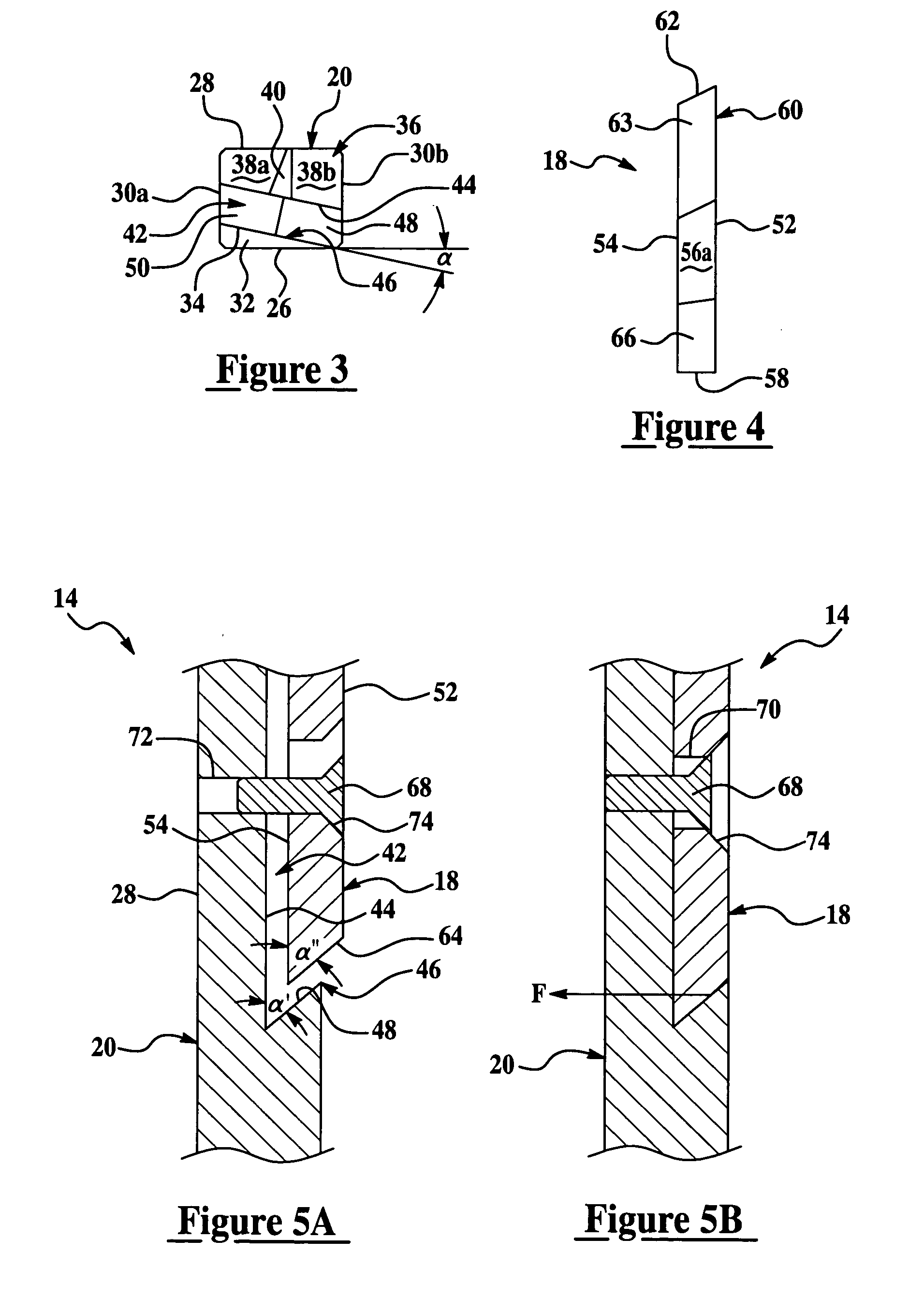
[0041] Turning now to FIGS. 10-13, the cutting insert 218 and holder 220 are shown where like numerals increased by 200 represent like structure with respect to the embodiment shown in FIGS. 1-4. In the embodiment shown, the holder 220 includes a pocket 242 defined by a back surface 244 and a lip member 246. In the embodiment shown, the lip member 246 is a bottom angled surface 280 that intersects the back surface 244 at an acute angle, α′, as represented in FIG. 5A. The cutting insert 218 includes a bottom angled surface 282 that intersects the back surface 254 of the cutting insert 218 at an acute angle, α″. The bottom angled surface 282 is generally perpendicular to the side surfaces 256a, 256b of the cutting insert 218. The bottom angled surface 218 is generally complimentary to the bottom angled surface 280 of the holder 220 such that the bottom angled surfaces 280, 282 abut against each other when the cutting insert 218 is coupled to the holder 220. Also, the cutting insert 21...
PUM
| Property | Measurement | Unit |
|---|---|---|
| Force | aaaaa | aaaaa |
| Angle | aaaaa | aaaaa |
Abstract
Description
Claims
Application Information