Battery pack

Active Publication Date: 2007-06-21
PANASONIC EV ENERGY CO LTD
View PDF4 Cites 29 Cited by
  • Summary
  • Abstract
  • Description
  • Claims
  • Application Information

AI Technical Summary

Benefits of technology

[0012] The present invention provides a battery pack which maintains the

Problems solved by technology

However, in the case of a configuration where the equipment box 40 is located on one side of the battery stack 20, since the battery stack 20 is heavier than the equipment box 40, the centroid of the entire battery pack 10 is biased towards the battery stack 20, which creates an imbalance in the weight of the vehicle when the battery stacked 20 is mounted in the vehicle.
How

Method used


Image

  • Battery pack
  • Battery pack
  • Battery pack

Examples


Embodiment Construction

[0028] An embodiment of the present invention will be described hereinbelow by reference to the drawings.

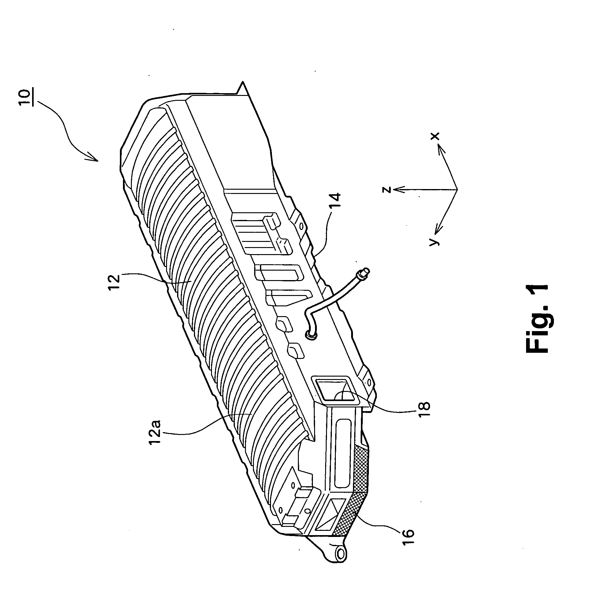
[0029]FIG. 1 is an external perspective view of a battery pack 10 according to a present embodiment. A battery case, which is an enclosure of the battery pack 10, has an upper case 12 for covering an upper portion of a battery stack and a lower case 14 for covering a lower portion of the same. The battery pack 10 has a built-in battery assembly (a battery stack). A plurality of battery modules, each formed from one or a plurality of unit cells such as a nickel-metal hydride battery or the like, are arranged (stacked) in parallel while a cooling passage is formed so as to pass through the modules. End members provided at both ends of the cooling passage are assembled in a tied manner, thereby forming the battery assembly where battery modules are electrically connected in series with each other. Moreover, a cooling fan is disposed in the battery pack 10. An air intake 16 is forme...


PUM


Abstract

A battery pack to be mounted on a vehicle. The battery pack has a battery stack. A cooling fan, a fan relay, and a main relay (−) are disposed on one side of the battery stack. A control module, a register, a main relay (+), and a pre-charge relay are disposed on the other side of the same. As a result of devices being disposed on both sides of the battery stack, the weight of the battery pack is adjusted to the neighborhood of the center of the battery pack.

Description

PRIORITY INFORMATION [0001] This application claims priority to Japanese Patent Application No. 2005-366901, filed on Dec. 20, 2005, which is incorporated herein by reference in its entirety. BACKGROUND OF THE INVENTION [0002] 1. Field of the Invention [0003] The present invention relates to a battery pack, and more particularly, to the structure of a battery pack mounted in a vehicle. [0004] 2. Related Art [0005] A battery pack is mounted on a hybrid electric vehicle, a fuel-cell-powered vehicle, or an electric vehicle for storing power to be supplied to a drive motor. A battery pack as a battery stack, and an equipment box with various pieces of equipment used for controlling the battery stack incorporated therein. [0006]FIG. 7 shows a plan view of a related-art battery pack 10. A battery stack 20 is formed by means of stacking a plurality of single cells, each of which is formed from a nickel-metal hydride battery, a lithium ion battery, or the like. An equipment box 40 is locate...

Claims


Application Information

Patent Timeline
IPC IPC(8): H01M10/50H01M2/12B60R16/04B60K1/04B60K6/28H01M10/60H01M10/613H01M10/625H01M10/647H01M10/651H01M10/6563H01M50/204
CPCB60R16/04H01M2/1083H01M10/46H01M10/5004H01M10/5067H01M10/6563H01M10/613Y02E60/10H01M50/204
Inventor MARUKAWA, SHUHEIETO, TOYOHIKOMISU, MASAHIRO
Owner PANASONIC EV ENERGY CO LTD
Why Eureka
Try Eureka