Electrical connector

a technology of electrical connectors and connectors, applied in the direction of coupling device details, coupling device connections, electric discharge lamps, etc., can solve the problems of easy cross talk, difficult to transmit signals at a high speed, elasticity problems, etc., and achieve the effect of reducing the size of the devi

Inactive Publication Date: 2007-06-21
HIROSE ELECTRIC GROUP
View PDF2 Cites 23 Cited by
  • Summary
  • Abstract
  • Description
  • Claims
  • Application Information

AI Technical Summary

Benefits of technology

[0016]According to the present invention, in the electrical connector using the one point contact type connector, while the stroke problem is effectively solved, the device size can be reduced.

Problems solved by technology

As a result, cross talk easily occurs, and it is difficult to transmit signals at a high speed.
While a so-called one point contact type connector contacting with a mating terminal at one point is used to reduce a device size, problems characteristic to the one point contact type connector such as a strength problem and an elasticity problem are solved.

Method used


Image

  • Electrical connector
  • Electrical connector
  • Electrical connector

Examples


Embodiment Construction

[0036]Hereunder, embodiments of the present invention will be explained with reference to the accompanying drawings.

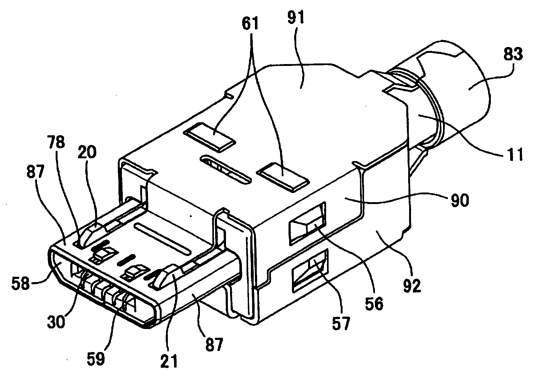
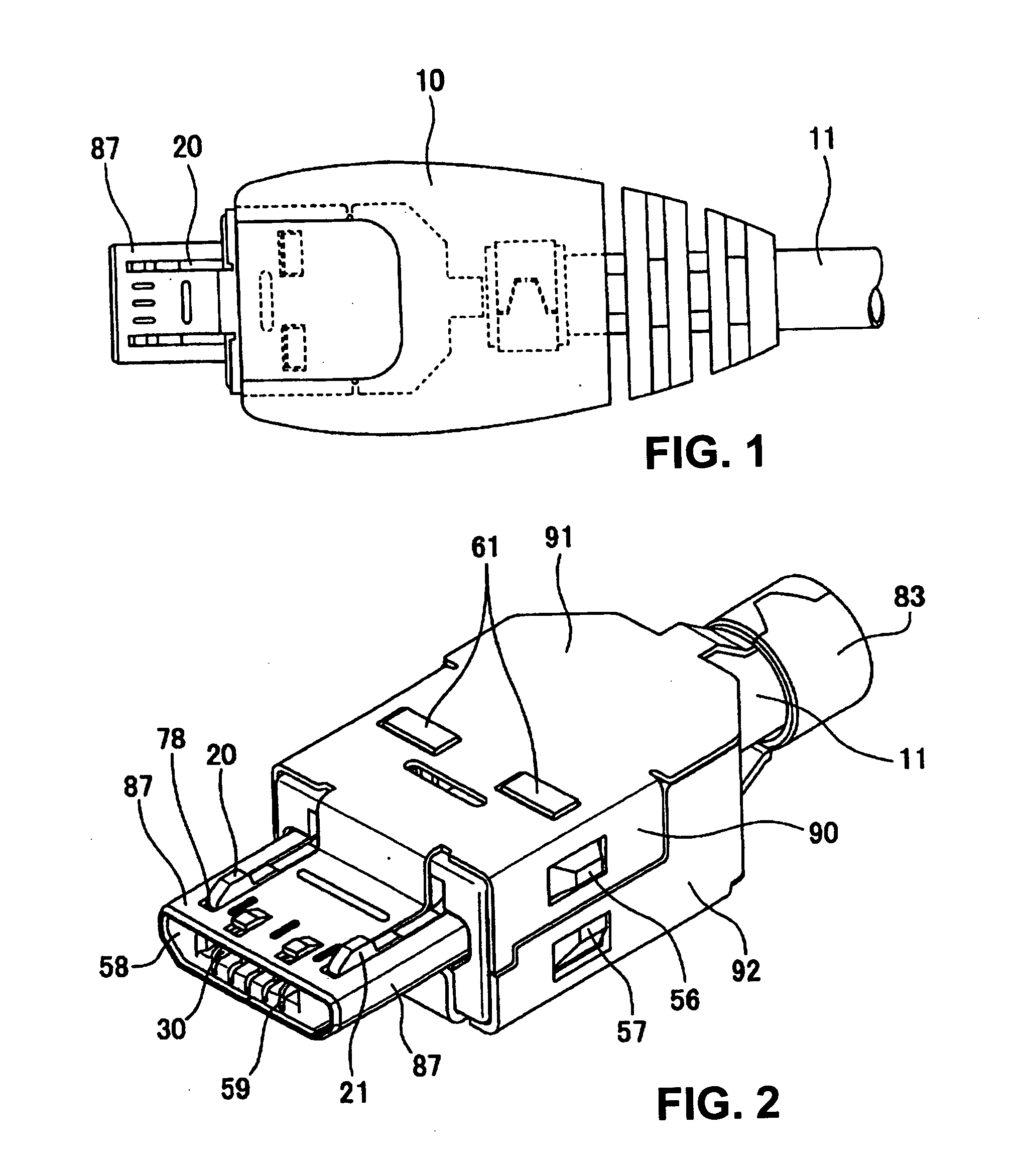
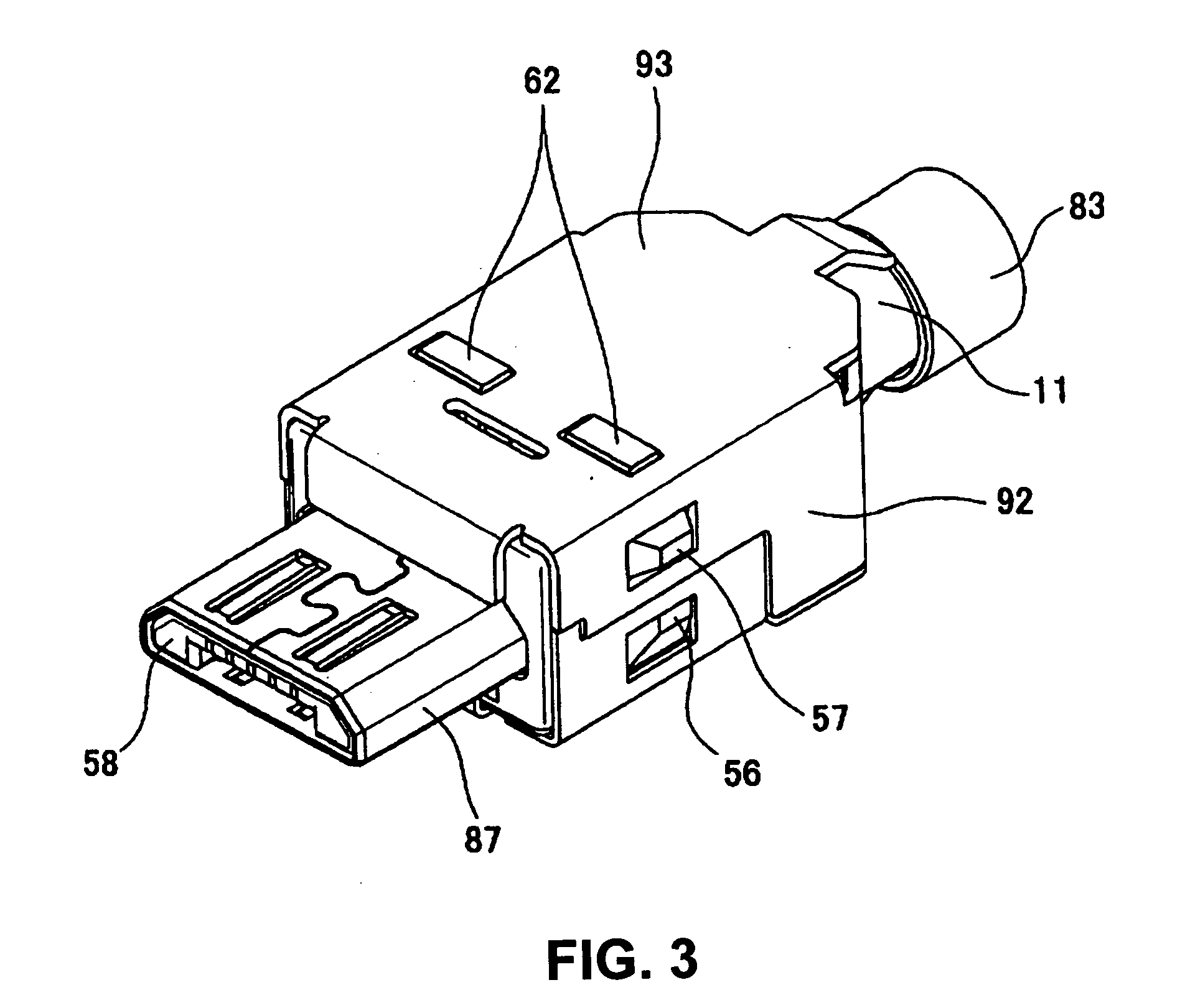
[0037]In FIG. 1, a plane view of an electrical connector 1 according to the present invention is shown. In FIGS. 2 and 3, an upper perspective view and a lower perspective view of the electrical connector 1 before over mold are shown, respectively. Further, in FIG. 4, an exploded perspective view of the electrical connector 1 before over mold is shown.

[0038]As apparent from FIG. 18 (described later), the electrical connector 1 is used as a so-called plug side connector. In an actual use, the electrical connector 1 is detachably fitted into a receptacle side connector (mating connector) 2 disposed on a substrate 101.

[0039]The electrical connector 1 mainly includes a housing 50 integrally formed of a resin and the likes; a first shell 70 (first cover portion) and a second shell 72 (second cover portion) used as a cover of the housing 50; terminals 30 with a plate shape a...


PUM


Abstract

An electrical connector includes a housing and a plurality of terminals having a plate shape to be attached to the housing in parallel with a narrow pitch. The plurality of the terminals has holes at opposing portions thereof in a pitch direction such that opposing areas between adjacent terminals is reduced. The housing has a groove bridging over the plurality of the terminals in the pitch direction such that a space is formed between the adjacent terminals.

Description

BACKGROUND OF THE INVENTION AND RELATED ART STATEMENT[0001]The present invention relates to an electrical connector. More specifically, the present invention relates to an electrical connector having a plurality of terminals arranged in parallel with a narrow pitch.[0002]For example, in the fields of mobile phones, digital cameras, PDA, and the likes, reduction in a device size has been rapidly proceeding. Accompanying with this trend, requirement for reduction in a size of electrical connectors used for these devices has been increased. To reduce a size of an electrical connector, for example, when a plurality of terminals is arranged in parallel for use, narrowing a terminal pitch is generally tried. When the terminal pitch is narrowed, there may a case that the terminals arranged with a constant pitch function as if capacitors. As a result, cross talk easily occurs, and it is difficult to transmit signals at a high speed.[0003]To solve this problem, conventionally, as disclosed i...

Claims


Application Information

Patent Timeline
Patent Type & Authority Applications(United States)
IPC IPC(8): H01R13/627
CPCH01R23/10Y10S439/941H01R13/6461H01R13/6476H01R24/62
Inventor KOYAMA, RYOZO
Owner HIROSE ELECTRIC GROUP
Why Eureka
Try Eureka