
Communication Terminal, Mobile Communication System, and Communication Control Method

Active Publication Date: 2007-06-21
KYOCERA CORP
View PDF17 Cites 38 Cited by
  • Summary
  • Abstract
  • Description
  • Claims
  • Application Information

AI Technical Summary

Benefits of technology

[0009] The present invention has been conceived in light of these circumstances, and an object thereof is to provide a communication terminal, a mobile communication system, and a communication control method for preventing the transmission power amplifier of one communication terminal (local station) from overheating by using another communication terminal (remote station) located in an inter-communicable range as a relay station.
[0018] According to the present invention, the transmission power amplifier of one communication terminal (local station) can be prevented from overheating by using another communication terminal (remote station) located in an inter-communicable range as a relay station while still continuing communication. This improves the user experience.

Problems solved by technology

In the wireless communication system described in Japanese Unexamined Patent Application Publication, First Publication No. 2002-171287, any obstacle, such as a tall building, between the base station and a communication terminal may interfere with radio reception by the communication terminal, and in such a poor reception state a high transmission output is maintained.
This may cause the transmission power amplifier to overheat.

Method used


Image

  • Communication Terminal, Mobile Communication System, and Communication Control Method
  • Communication Terminal, Mobile Communication System, and Communication Control Method
  • Communication Terminal, Mobile Communication System, and Communication Control Method

Examples


Embodiment Construction

[0027] One embodiment according to the present invention will now be described with reference to the drawings.

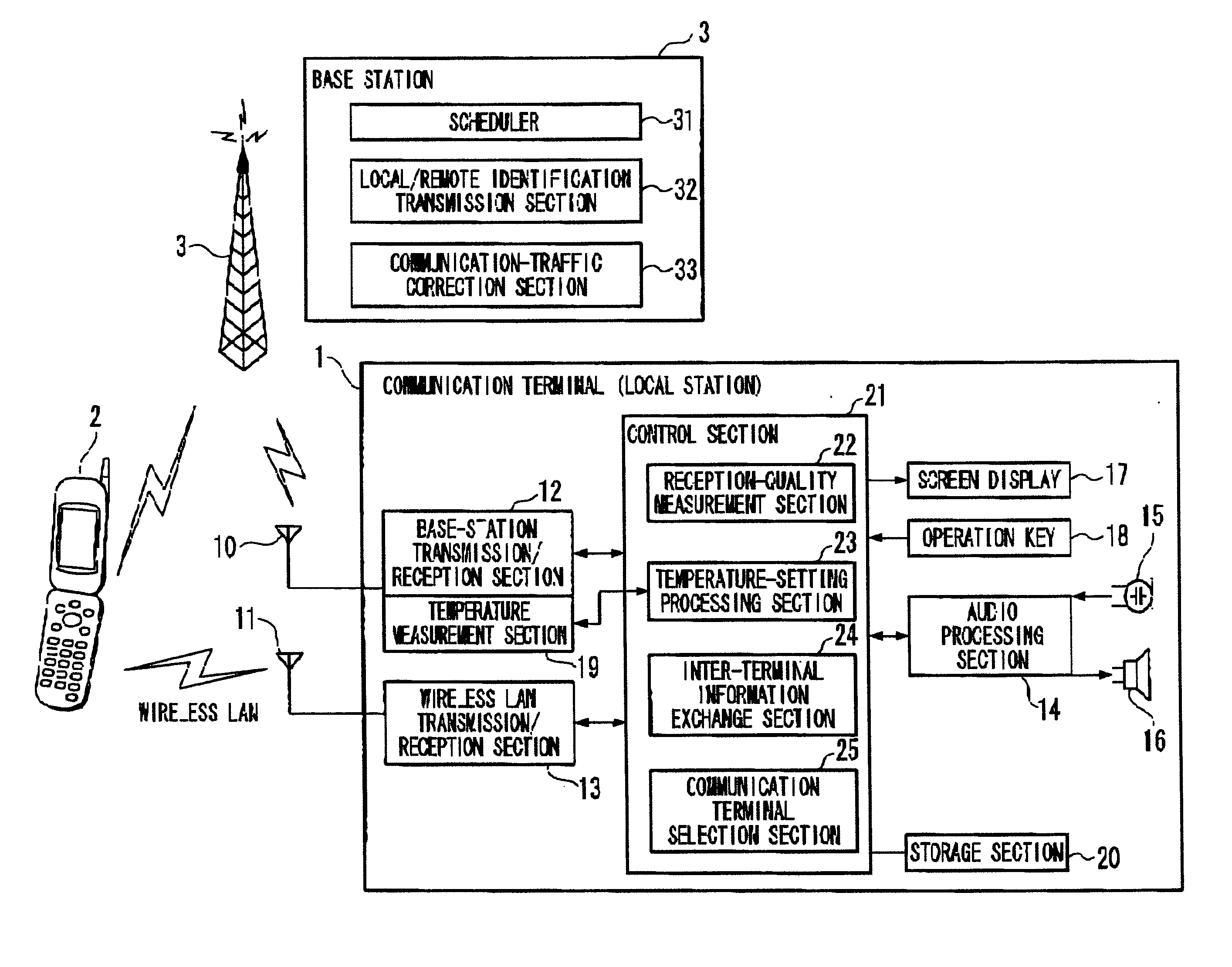
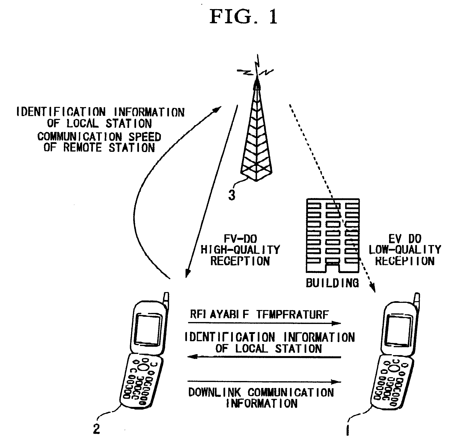
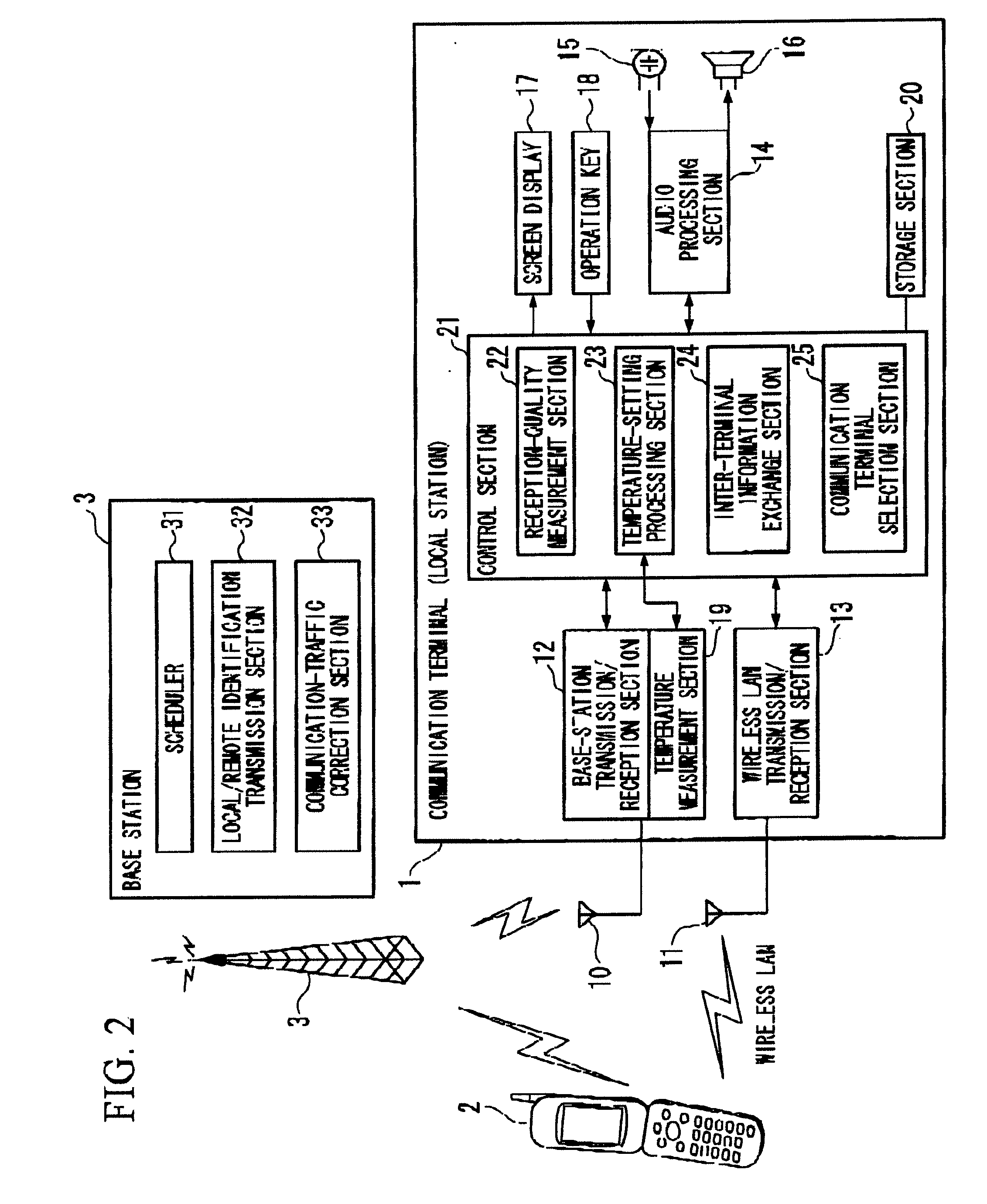
[0028]FIG. 1 is a diagram depicting a preferred overall structure of a mobile communication system according to one embodiment of the present invention. FIG. 1 shows an exemplary positional relationship among a base station 3, a mobile communication terminal 1 (hereinafter, referred to as a communication terminal) serving as a local station, and a communication terminal 2 serving as a remote station. This embodiment is described by way of example of a mobile communication system employing a communication technique for controlling the transmission power of a communication terminal according to the reception state at that communication terminal, as typified by the CDMA2000 1xEV-DO standard. Thus, the current description assumes that the communication terminal 1 serving as the local station suffers from low-quality reception due to an obstacle, such as a building, located betw...


PUM


Abstract

A communication terminal includes a first wireless communication unit that communicates with a base station; a second wireless communication unit that communicates with another communication terminal including an equivalent of the first wireless communication unit; a temperature measurement unit; and a control unit that selects one of the first wireless communication unit and the second wireless communication unit according to a temperature measured by the a temperature measurement unit.

Description

CROSS-REFERENCE TO RELATED APPLICATION [0001] Priority is claimed on Japanese Patent Application No. 2005-285231, filed Sep. 29, 2005, the content of which is incorporated herein by reference. BACKGROUND OF THE INVENTION [0002] 1. Field of the Invention [0003] The present invention relates to a communication terminal, a mobile communication system, and a communication control method. [0004] 2. Description of the Related Art [0005] Wireless communication systems for variably controlling downlink (from base station to terminal) communication speeds (hereinafter, referred to as “downlink speeds”) according to a reception state at each communication terminal are known, as typified by CDMA2000 1xEV-DO. These wireless communication systems employ a wireless communication technique for achieving a tradeoff between downlink speed, and, for example, error resilience by exploiting a plurality of modulation techniques, spread rates, etc., so that a higher communication speed can be provided ac...

Claims


Application Information

Patent Timeline
IPC IPC(8): H04Q7/20H04W52/00H04W76/04H04W88/04H04W92/18
CPCH04L25/0228H04L25/0262H04W48/18H04W76/023H04W88/04H04W92/18H04W52/0216H04W52/0219H04W76/14Y02D30/70H04W76/20
Inventor MATSUMURA, TAKASHIMIKI, TOMOHIRO
Owner KYOCERA CORP
Learn More