
Self-cleaning sample extraction system

a sample extraction and self-cleaning technology, applied in the field of self-cleaning sample extraction system, can solve the problems of system contamination, filter clogging of filter a sample taken from a process stream, and system clogging, so as to facilitate filter cleaning and reduce clogging

Active Publication Date: 2007-06-28
PARKER INTANGIBLES LLC
View PDF5 Cites 23 Cited by
  • Summary
  • Abstract
  • Description
  • Claims
  • Application Information

AI Technical Summary

Benefits of technology

The present invention provides a sampling apparatus that can self-clean when excess sample is flushed back into the process stream. The apparatus includes a sample probe, an extraction cylinder with a movable piston, and a sampling valve. A filter assembly is interposed between the sample probe and the sampling valve for filtering undesired substances from the fresh sample. A controller is provided for controlling the actuator and the sampling valve. The invention also provides a method for extracting samples from a process stream and cleaning the filter of undesired substances during the process.

Problems solved by technology

In many online sampling apparatus the sample is discarded and this may present an environmental issue depending on the nature of the sample.
In some systems, provision is made for reintroducing the sample back into the process stream, but these systems may be plagued by sample contamination.
Another problem is that filters used to filter a sample taken from a process stream become clogged, requiring frequent replacement and / or cleaning.

Method used


Image

  • Self-cleaning sample extraction system
  • Self-cleaning sample extraction system
  • Self-cleaning sample extraction system

Examples


Embodiment Construction

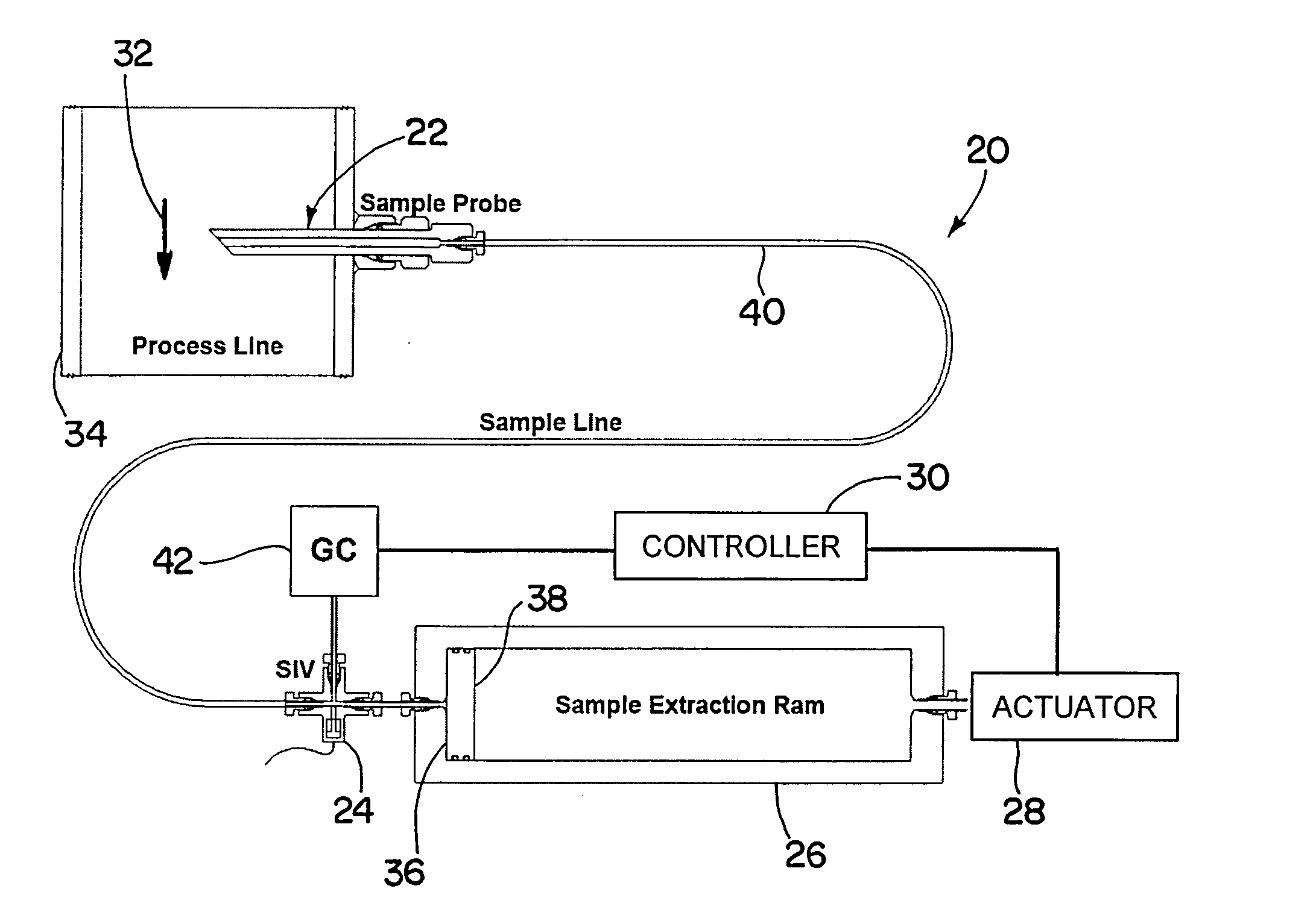
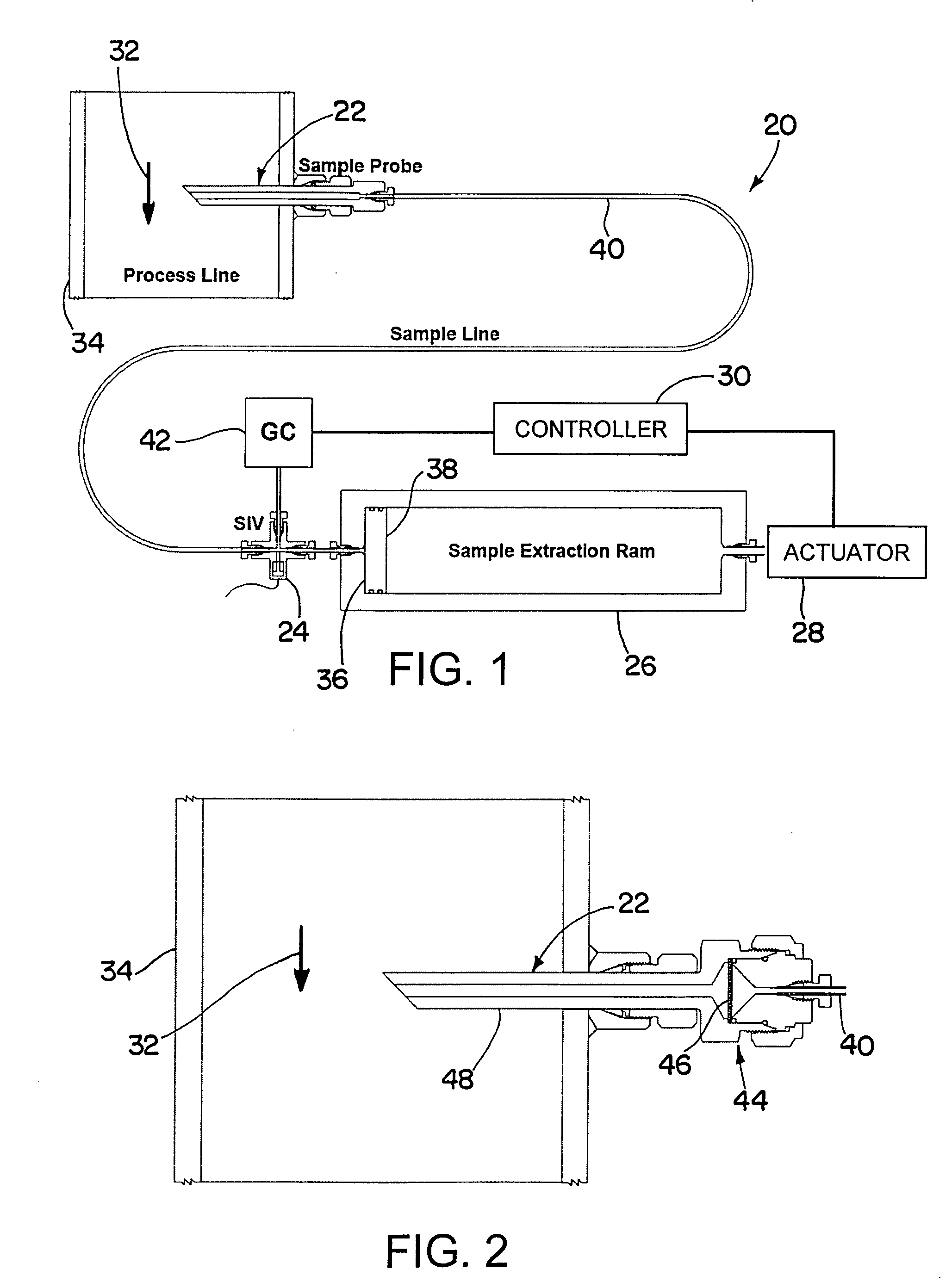
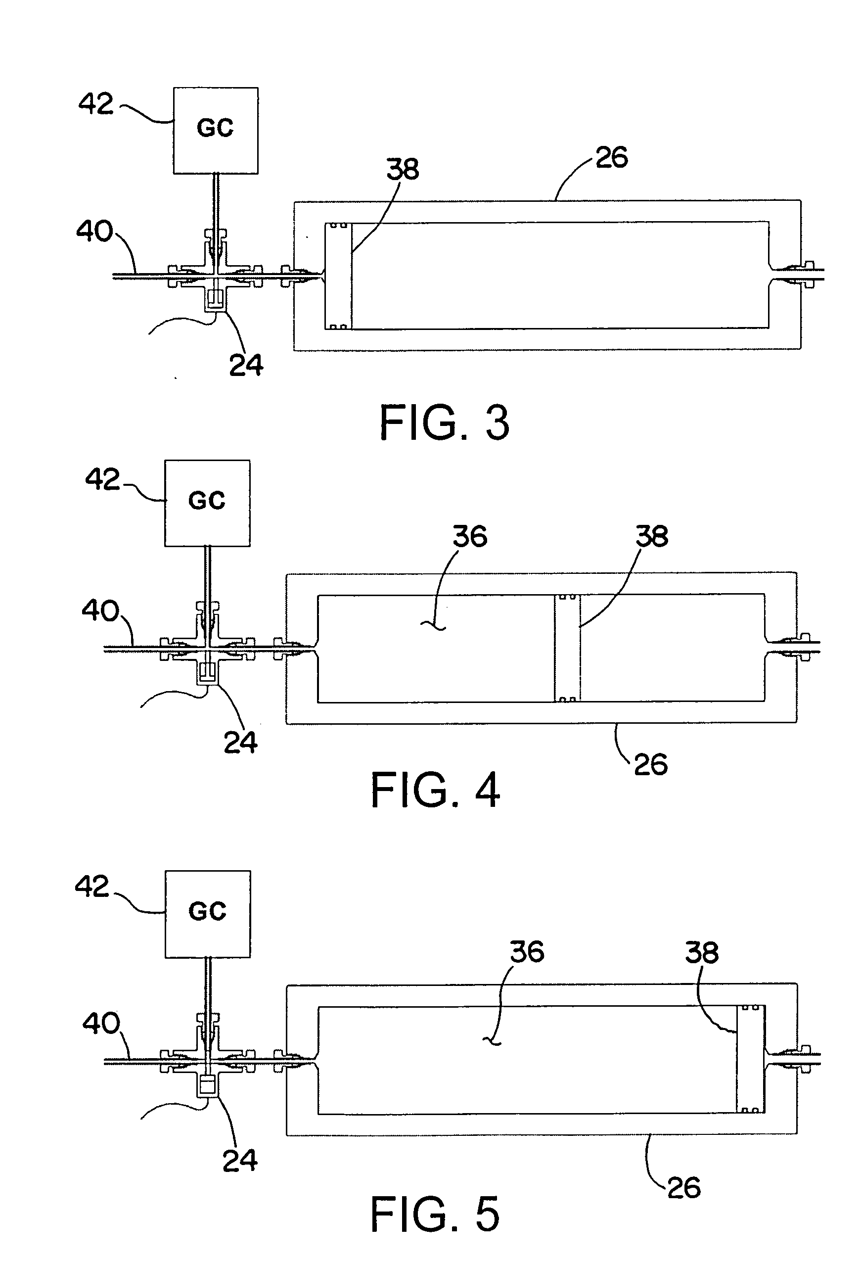
[0024] Referring now in detail to the drawings and initially to FIG. 1, an exemplary sampling apparatus according to the invention is generally designated by reference numeral 20. The apparatus 20 generally comprises a sample probe 22, a sampling valve 24, an extraction cylinder 26, an actuator 28 and a controller 30. The sample probe is insertable into a process stream 32 flowing through a conduit 34. The extraction cylinder 26, also herein referred to as a sample extraction ram (SER), includes a variable volume chamber 36 and a piston 38 movable by the actuator 28 back and forth in the cylinder to increase and decrease the volume of the variable volume chamber. The sampling valve 24 is connected between the extraction cylinder and the sample probe, with a sample line 40 connecting the sampling valve to the sample probe. The variable volume chamber having a capacity substantially greater than the combined volumes of the sample probe, sampling valve and sample line, whereby fresh sa...


PUM

PropertyMeasurementUnit
volumeaaaaaaaaaa
volumesaaaaaaaaaa
speedaaaaaaaaaa

Abstract

A sampling apparatus for use with a sample analyzer comprises a sample probe insertable into a process stream, and an extraction cylinder including a variable volume chamber and a piston movable by an actuator back and forth in the cylinder to increase and decrease the volume of the variable volume chamber. A sampling valve is connected between the extraction cylinder and the sample probe, with a sample line connecting the sampling valve to the sample probe, and the variable volume chamber having a capacity substantially greater than the combined volumes of the sample probe, sampling valve and sample line. A filter assembly is interposed between the sample probe and sampling valve for filtering undesired substances from the fresh sample prior to the fresh sample reaching the sampling valve, and a controller is provided for controlling the actuator and the sampling valve, first to move the piston at a first rate to increase the variable volume chamber sufficiently to draw fresh sample from the process stream and past the sampling valve, then to operate the sampling valve for injecting fresh sample into the sample analyzer, and thereafter to move the piston at a second rate greater than the first rate to decrease the variable volume chamber to flush excess sample back into the process stream and clean the filter of undesired substances filtered from the fresh sample.

Description

RELATED APPLICATIONS [0001] This application claims the benefit of U.S. Provisional Application No. 60 / 736,484 filed Nov. 14, 2005, which is hereby incorporated herein by reference.FIELD OF THE INVENTION [0002] The invention herein described relates generally to a self-contained on-line sampling apparatus that returns a sample after testing to the process stream and which has a self-cleaning feature. BACKGROUND [0003] On-line analysis of process streams is used for a variety of reasons, including process control and quality assurance. Typically a sample is withdrawn from the process stream and injected by a sampling valve into an analytical instrument. In many online sampling apparatus the sample is discarded and this may present an environmental issue depending on the nature of the sample. In some systems, provision is made for reintroducing the sample back into the process stream, but these systems may be plagued by sample contamination. Another problem is that filters used to fil...

Claims


Application Information

Patent Timeline
Patent Type & Authority Applications(United States)
IPC IPC(8): G01N1/14
CPCG01N1/2035G01N35/1004
Inventor GIBSON, JAMESRUIZ, FRANK
Owner PARKER INTANGIBLES LLC
Learn More