
Method of manufacturing speaker edge member

a manufacturing method and speaker technology, applied in the field of manufacturing methods of speaker edge members, can solve the problems of large negative pressure within the speaker cavity, collapse, and large vibration of the diaphragm, and achieve the effect of reducing manufacturing costs and shortening manufacturing tim

Inactive Publication Date: 2007-06-28
PIONEER CORP +1
View PDF2 Cites 11 Cited by
  • Summary
  • Abstract
  • Description
  • Claims
  • Application Information

AI Technical Summary

Benefits of technology

[0011] The present invention makes it one of its tasks to solve the above-discussed problem. Namely, it is an object of the present invention to improve a speaker edge member manufacturing process in which a substrate is introduced into an edge member formation material by virtue of insertion molding, to prevent a trouble such as a crack in a parting line or the like, thus shortening a manufacturing time and thus reducing a manufacturing cost.

Problems solved by technology

However, with regard to a high power high-output speaker such as sub-woofer, its diaphragm usually has a large vibration and thus there is a large negative pressure within a speaker cavity.
As a result, an edge member, which should be kept in a convexly rolled shape, will become inwardly concave, undesirably causing a so-called “inward suction.” When there is such an “inward suction,” an edge shape designed for effecting a linear diaphragm displacement and preventing a lateral vibration and an inherent vibration of diaphragm, will get collapsed.
At this time, the diaphragm 20 will cause an abnormal vibration and edge member itself will have an inherent resonance, resulting in a problem that a distorted or abnormal sound would occur in a low-pitched sound area.
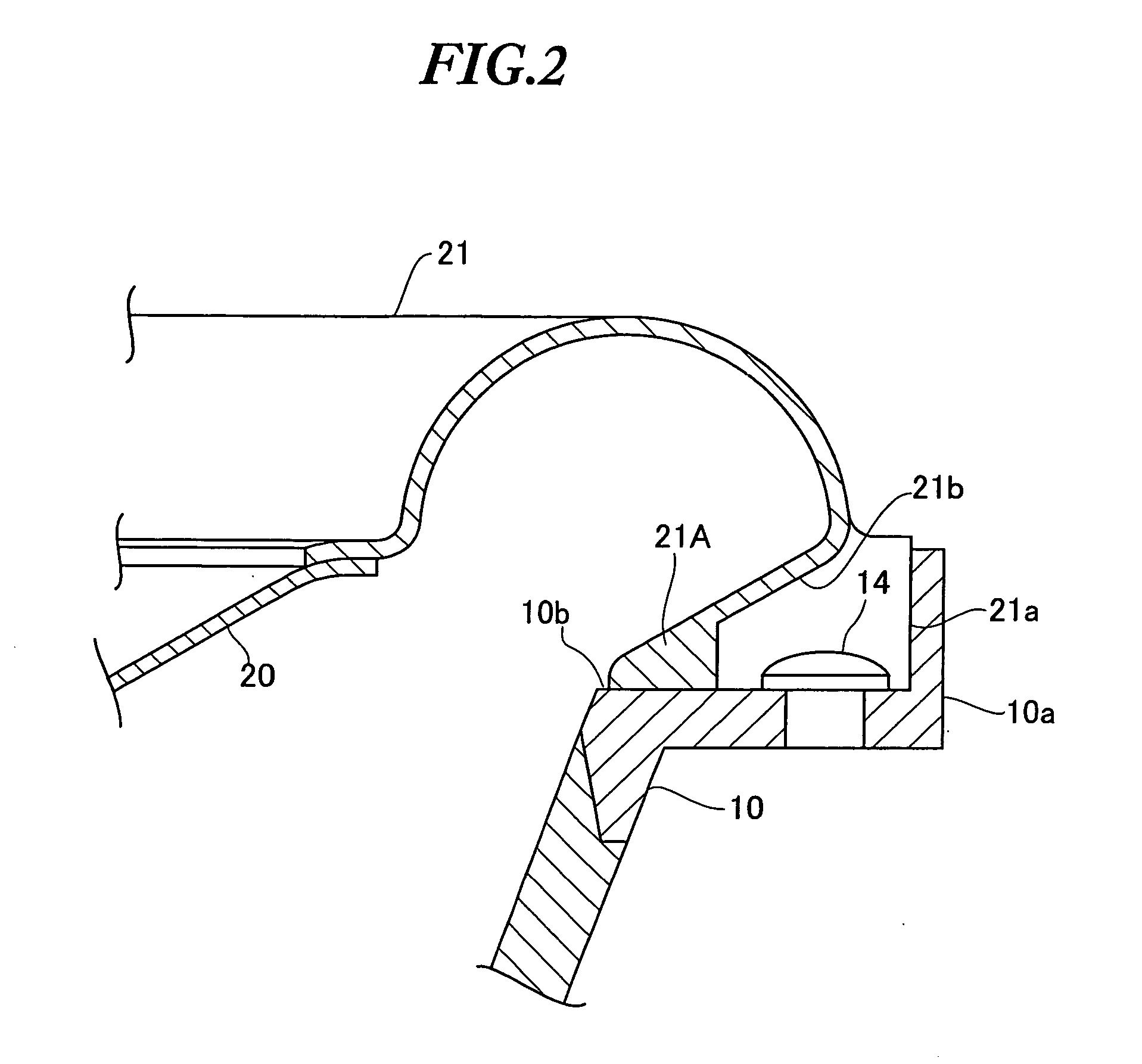
However, when the above-mentioned insertion molding is performed, the substrate 210B will undesirably protrude beyond a parting line 204, as shown in FIGS. 3B and 3C, resulting in a low strength at the protruding portion and thus causing the edge member to be broken or suffer from some other troubles.
Besides, after the foregoing insertion molding, it is necessary to carry out an additional step in which a cutter has to be used to cut off an unwanted substrate portion protruding beyond the parting line 204, thus requiring an additional time and an additional cost for carrying out such an additional step.

Method used


Image

  • Method of manufacturing speaker edge member
  • Method of manufacturing speaker edge member
  • Method of manufacturing speaker edge member

Examples


first embodiment

[0032]FIG. 4 provides views showing a speaker formed according to a first embodiment of the present invention. In more detail, FIG. 4A is a plan view and FIG. 4B is a sectional view taken along A-A line shown in FIG. 4A. FIG. 5A is an enlarged view showing an area around an edge member illustrated in FIG. 4B. FIG. 5B is a sectional view taken along B-B line shown in FIG. 4A. In the following description, the same structures and functions as those included in the speaker shown in FIG. 2 will be omitted.

[0033] As shown in FIGS. 4 and 5, a speaker 100 according to one embodiment of the preset invention is formed in a manner such that a central portion of a diaphragm 20 is fixed near an upper end of a coil bobbin 6, while an annular edge member 12 is connected with the outer edge portion of a diaphragm 20. The annular edge member 12 of the present embodiment includes an outer edge portion 12A, an arcade portion 12B, and an inner edge portion 12C. The outer edge portion 12A, the arcade ...

second embodiment

[0054]FIGS. 8A and 8B are sectional views showing a speaker edge member formed according to a second embodiment of the present invention. However, the following description will not explain structure and function which are substantially the same as those of the first embodiment. In more detail, FIG. 8 is a sectional view taken along A-A line of the speaker 10Oa shown in FIG. 4A, FIG. 8B is a sectional view taken along B-B line of the speaker 100a shown in FIG. 4A.

[0055] As shown in FIGS. 8A and 8B, an edge member 12g of the present embodiment is formed such that an outer edge portion 121c′ of a substrate 121B′ is located at an outer edge portion 12A of the edge member 12b, inwardly of the parting line 304 formed along a circumferential direction over the outer surface of the bent portion of the edge member 12g.

[0056] With regard to the edge member 12g having the above-described structure, since the outer edge portion 121c′ of the substrate 121B′ buried within the edge member forma...

third embodiment

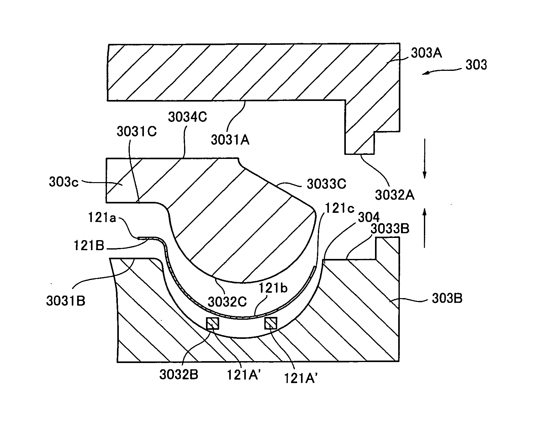
[0063]FIG. 12 provides views showing a speaker edge member formed according to a third embodiment of the present invention. In detail, FIG. 12A is a view showing a method of manufacturing a speaker edge member, and FIG. 12B is a view showing a speaker edge member manufactured in the speaker edge member manufacturing method shown in FIG. 12A.

[0064] In the speaker edge member manufacturing method according to the present embodiment, the inner circumferential side of the speaker edge member and the outer circumferential side of the speaker diaphragm are integrally formed together by virtue of an edge member formation material such as resin or the like. However, in the following description, the structure, function, and operation or the like which are substantially the same as foregoing embodiments will be omitted. At first, as shown in FIG. 12A, the diaphragm 20 and the edge member formation material 121A′ are placed in the die 303. In more detail, the outer edge portion 20a of the di...


PUM

PropertyMeasurementUnit
Timeaaaaaaaaaa
Distanceaaaaaaaaaa

Abstract

It is an object of the present invention to improve a speaker edge member manufacturing process in which a substrate is introduced into an edge member molding material by virtue of insertion molding, to prevent a trouble such as a crack on a parting line or the like, thus shortening a manufacturing time and thus reducing a manufacturing cost. An edge member molding die has at least a male die and a female die, as well as an annular cavity formed corresponding to the speaker edge member within the die when the die is closed, while a dividing line is formed by virtue of the dividing surfaces of the male die and the female die, along a circumferential direction in a generally central portion of the annular cavity. An edge member manufacturing method comprises the steps of: attaching the substrate into the edge member molding die; introducing the edge member formation material into the edge member molding die before or after attaching the substrate into the edge member molding die; heating / pressurizing the substrate and the edge member formation material in the edge member molding die so as to obtain a molded edge member. At this time, the outer edge portion of the substrate is located in a position separated a predetermined distance from the dividing line of the die.

Description

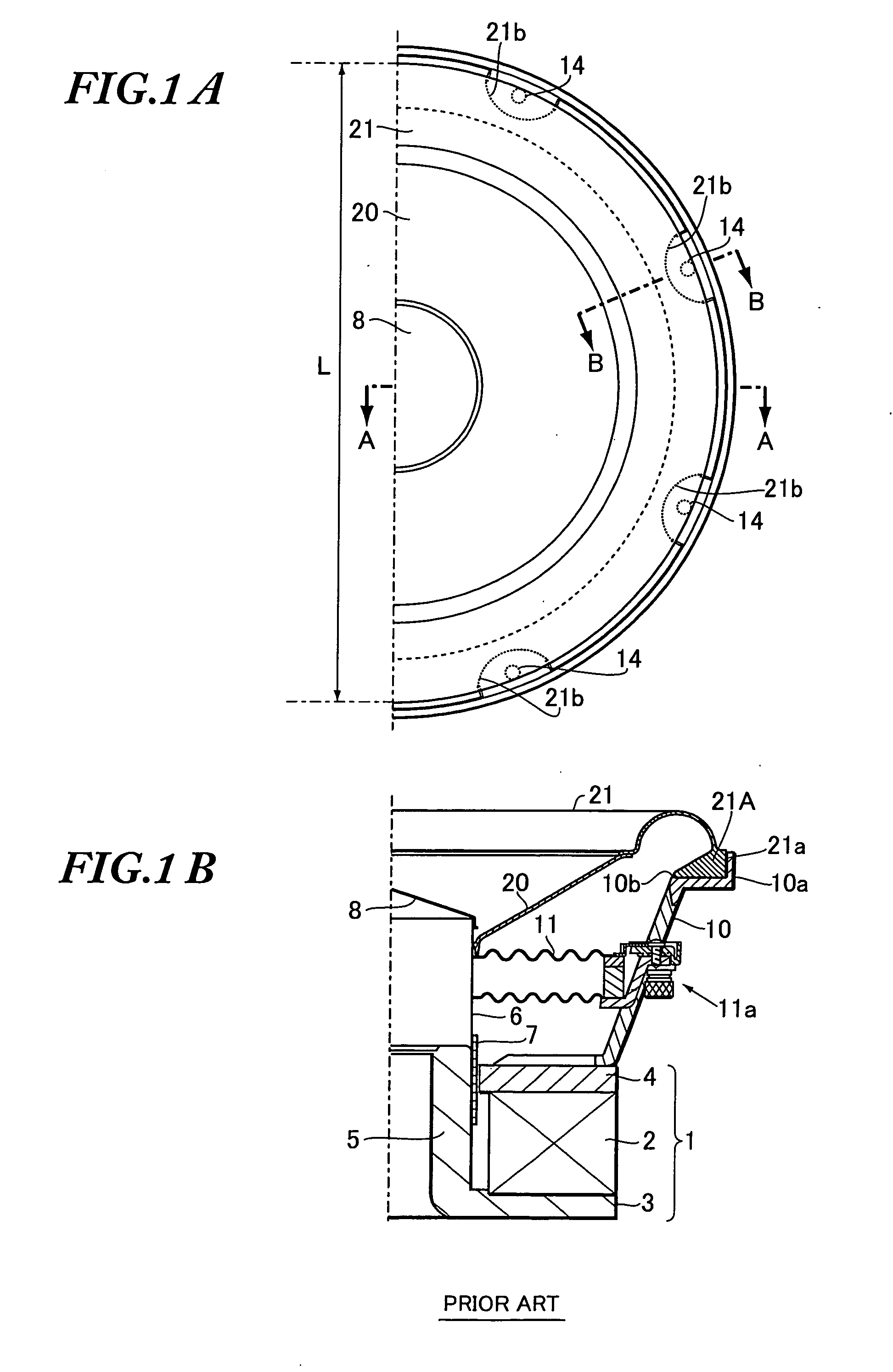
BACKGROUND OF THE INVENTION [0001] The present invention relates to a method of manufacturing a speaker edge member. [0002] The present application claims priority from Japanese Application No. 2005-373232, the disclosure of which is incorporated herein by reference. [0003] A speaker for reproducing music or the like has a general structure shown in FIGS. 1A, 1B, and FIG. 2 (disclosed in Japanese Unexamined Patent Application Publication No. 2003-111189). As shown, the conventional speaker has a magnetic circuit 1 formed by including a magnet 2, a lower plate 3, and an upper plate 4. An annular magnetic gap is formed between the upper plate 4 and a center pole 5 uprightly standing in the center of the lower plate 3. A coil bobbin 6 wound by a voice coil 7 is provided in a manner such that the voice coil 7 is located with in the magnetic gap. Further, the coil bobbin 6 is connected with one edge of a damper 11, while a damper support portion 11a supporting the other edge of the dampe...

Claims


Application Information

Patent Timeline
IPC IPC(8): B29C45/14
CPCH04R31/003H04R2231/001H04R2231/003H04R2307/204
Inventor SATO, SEIYAMATSUDA, KYOICHI
Owner PIONEER CORP
Learn More