
System and architecture for controlling lighting through a low-voltage bus

a low-voltage bus and system technology, applied in the direction of electric variable regulation, process and machine control, instruments, etc., can solve the problems of system failure, lighting project lighting problems, and difficulty in running these low-voltage lines

Inactive Publication Date: 2007-06-28
FINELITE
View PDF15 Cites 27 Cited by
  • Summary
  • Abstract
  • Description
  • Claims
  • Application Information

AI Technical Summary

Benefits of technology

"The present invention provides a decentralized low-voltage bus for managing a load circuit with lights. The bus includes multiple control units that integrate a sensor and a control switch. The control units and cables have RJ45 interconnects for electrically coupling them. The bus also includes a second sensor and a relay assembly for interfacing the bus, lights, and an external power source. The invention also includes a light control hub for controlling the levels of light output from light fixtures based on received control signals from low-voltage periphery devices. The kit includes a controller unit, a hub, and interconnecting cables for coupling the controller unit to the hub. The technical effects of the invention include efficient management of low-voltage loads, flexible control of light fixtures, and improved safety compliance."

Problems solved by technology

Running these low voltage lines can be difficult, especially when walls and / or ceilings of the building are made of concrete, as is often the case with office buildings and schools.
In addition, existing wiring, electrical boxes and receptacles are generally not universal or standardized and, therefore, each retrofit installation of energy saving devices in a building is typically a customized project, wherein all wire leads are separately connected, taped and secured with nuts.
In addition to the installation challenges, low voltage wiring that is exposed or tacked to walls and ceilings can be subject to physical disturbances that result in system failures.
Problems also exist for new construction lighting projects.
Lighting control system for new buildings are generally very expensive both for entire building systems that require full-time support and dedicated controls for each single function.

Method used


Image

  • System and architecture for controlling lighting through a low-voltage bus
  • System and architecture for controlling lighting through a low-voltage bus
  • System and architecture for controlling lighting through a low-voltage bus

Examples


Embodiment Construction

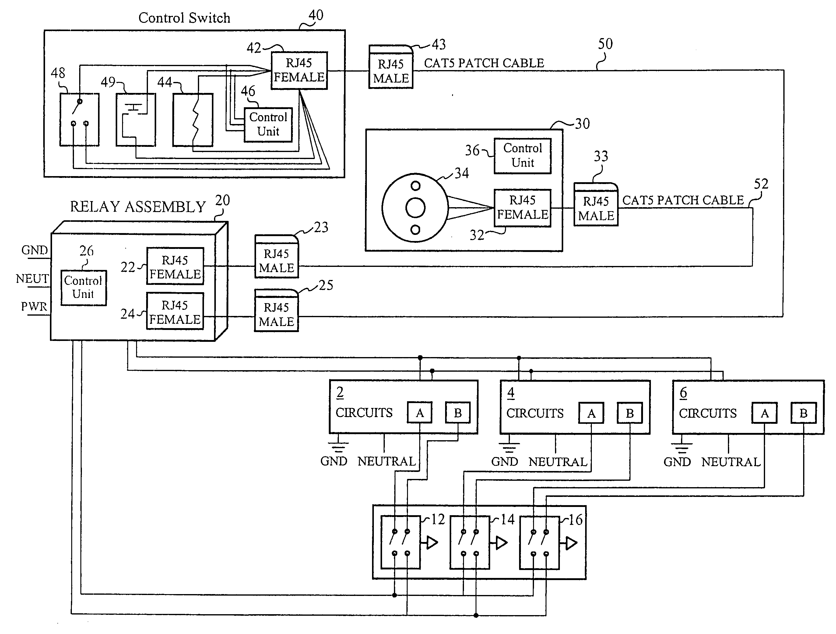
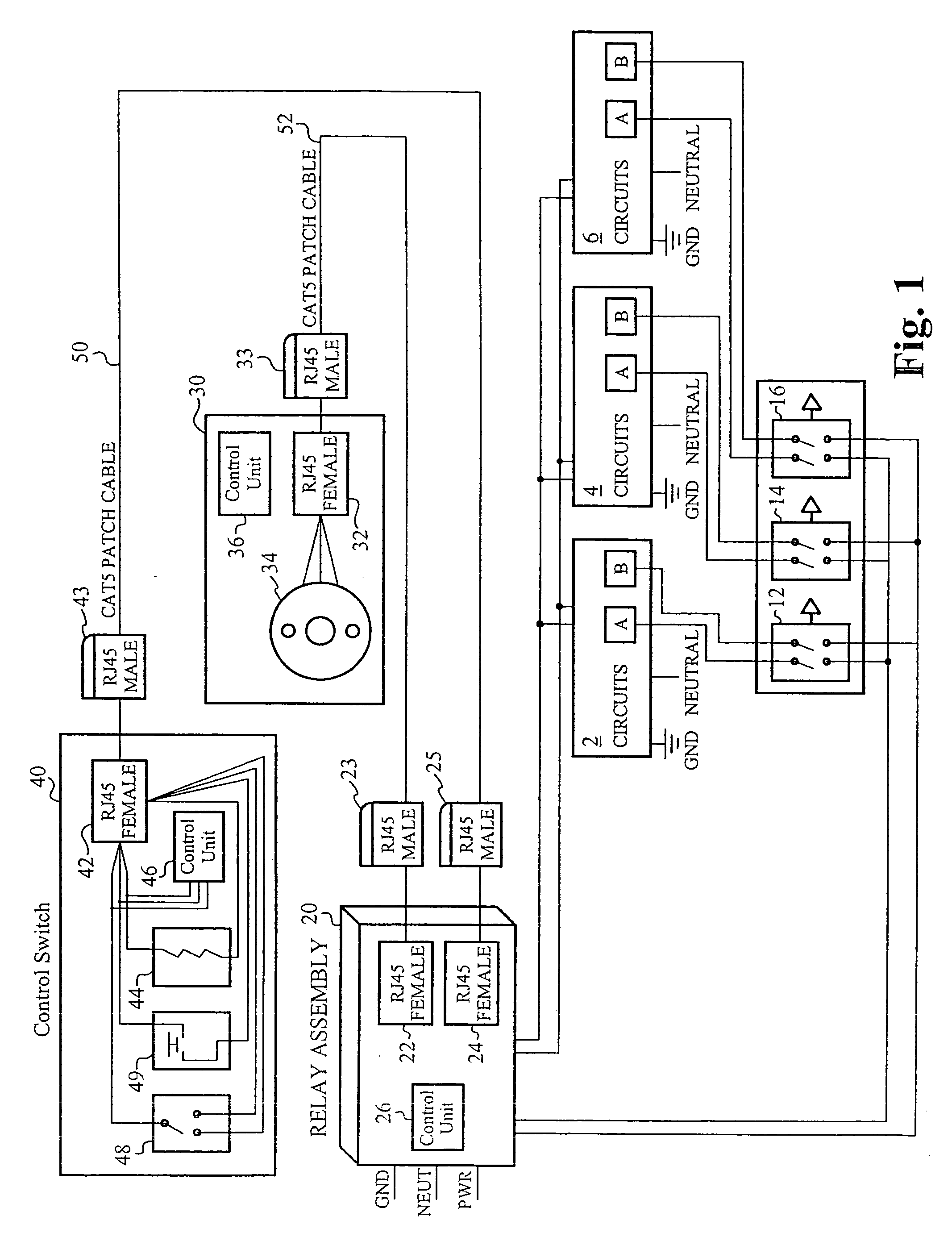
[0018] Embodiments of the present invention are directed to a system and an architecture for supporting and managing load circuits with a low-voltage bus. The low-voltage bus is configured to integrate low-voltage periphery devices, such as motion sensors, light sensors, other sensor devices, control switches and / or any other devices that are configured to control power to light fixtures or appliances. In accordance with a preferred embodiment of the invention, the low-voltage bus is configured to integrate at least one sensor and at least one control switch, such as a dimmer switch, to control and manage power output to light fixtures, such as over-head fluorescent lights.

[0019] In accordance with the embodiments of the present invention, the system operates under what is referred to herein as a decentralized architecture. In a decentralized architecture there are a plurality of node locations for integrating the light fixtures, sensors, and control switches, referred to herein as...


PUM


Abstract

A system and architecture for managing lighting through a seamless low-voltage bus network is disclosed. The system comprises a plurality of control units that serve as nodes for integrating devices, such as light fixtures, control switches and sensors into the bus. Each of the control units preferably includes a printed circuit board and node interconnects for assembling the low-voltage bus and for integrating the devices. Alternatively, the system comprises a central hub with a master printed circuit control board and a plurality of interconnects for assembling the bus and for integrating the devices.

Description

RELATED APPLICATIONS [0001] This Application is a continuation application of the co-pending U.S. patent application Ser. No. 10 / 927,400, titled “SYSTEM AND ARCHITECTURE FOR CONTROLLING LIGHTING THROUGH A LOW-VOLTAGE BUS”, filed Aug. 25, 2004. The U.S. patent application Ser. No. 10 / 927,400, titled “SYSTEM AND ARCHITECTURE FOR CONTROLLING LIGHTING THROUGH A LOW-VOLTAGE BUS”, filed Aug. 25, 2004, claims priority under 35 U.S.C. 119(e) of the U.S. Provisional Patent Application Ser. No. 60 / 498,141, filed Aug. 26, 2003, and entitled “SYSTEM AN ARCHITECTURE FOR SUPPORTING AND MANAGING ELECTRICAL DEVICES” and the U.S. Provisional Patent Application Ser. No. 60 / 586,642, filed Jul. 9, 2004, and entitled “SYSTEM AN ARCHITECTURE FOR SUPPORTING AND MANAGING ELECTRICAL DEVICES.” The U.S. patent application Ser. No. 10 / 927,400, titled “SYSTEM AND ARCHITECTURE FOR CONTROLLING LIGHTING THROUGH A LOW-VOLTAGE BUS”, filed Aug. 25, 2004, the U.S. Provisional Patent Application Ser. No. 60 / 498,141, fi...

Claims


Application Information

Patent Timeline
Patent Type & Authority Applications(United States)
IPC IPC(8): H02J3/00G08B23/00H02J1/00
CPCH05B37/0254H05B47/18
Inventor CLARK, WALTERNUNOZ, DANIELBOURNE, DOUGLAS SCOTT
Owner FINELITE
Learn More