Control apparatus for electric vehicles

a technology for controlling apparatus and electric vehicles, applied in the direction of process and machine control, dynamo-electric converter control, instruments, etc., can solve the problems of voltage appearing on the power supply line becoming excessively high, voltage variations, etc., and achieves low cost and small size

Active Publication Date: 2007-06-28
DENSO CORP
View PDF12 Cites 32 Cited by
  • Summary
  • Abstract
  • Description
  • Claims
  • Application Information

AI Technical Summary

Benefits of technology

The objective of this invention is to create a controller for electric cars that can keep the electrical system stable while keeping it compact and affordable.

Problems solved by technology

The technical problem addressed in this patent relates to finding ways to prevent damage from high voltages resulting from unstable power sources when used in electric vehicles. Existing solutions like voltage boosting converters and smoothing capacitors have limitations in addressing these issues, leading to higher costs and difficulty in maintaining stability. Another issue related to balancing power between the two AC motors can further complicate matters.

Method used


Image

  • Control apparatus for electric vehicles
  • Control apparatus for electric vehicles
  • Control apparatus for electric vehicles

Examples


first embodiment

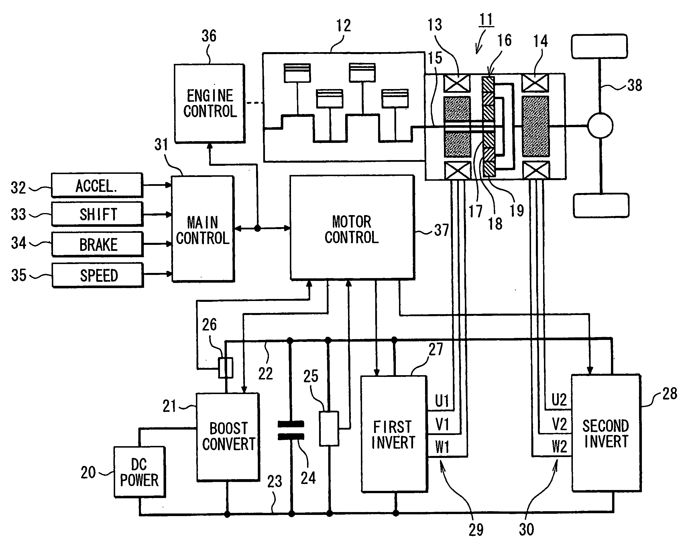
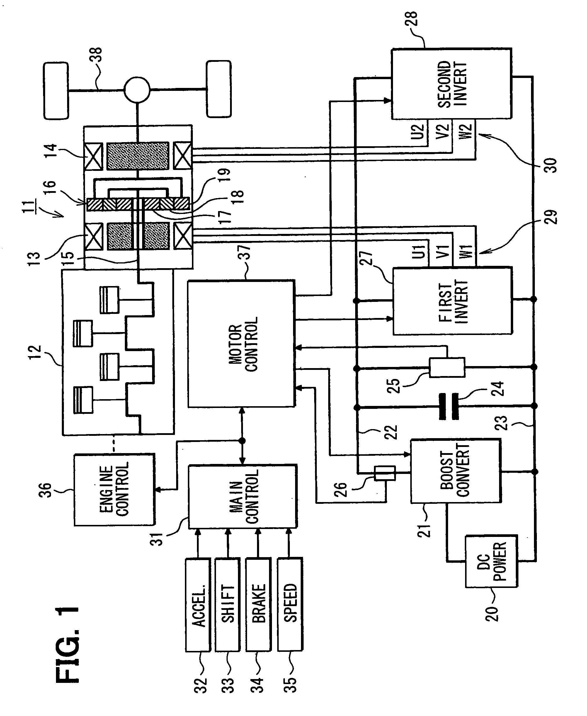
[0032] Referring first to FIG. 1, an electric vehicle 11 has an internal combustion engine 12 in addition to a first AC motor 13 and a second AC motor 14. Thus, the electric vehicle 11 is an engine / motor hybrid vehicle. The engine 12 and the second AC motor 14 are employed as a drive power source for driving the electric vehicle 11. Power generated by a crankshaft 15 of the engine 12 is divided into two paths by a planetary gear set 16. The planetary gear set 16 includes a sun gear 17, a planetary gear 18 and a ring gear 19. The sun gear 17 rotates at the center. The planetary gear 18 rotates along a circumference external to the sun gear 17 while revolving around the center of its own. The ring gear 19 rotates along a circumference external to the planetary gear 18. The planetary gear 18 is linked to the crankshaft 15 of the engine 12 through a carrier not shown in the figure. On the other hand, the ring gear 19 is linked to a rotation shaft of the second AC motor 14. The sun gear ...

second embodiment

[0072] The first embodiment may be modified in that, the positive d-axis current is supplied by setting the current vector to a stronger magnetic field side, when the torque command value T2* of the second AC motor 14 is substantially zero (within a predetermined range including zero), that is, when the reactive power is operated by controlling the current vector on the d-axis). This is for restricting the permanent magnet of the AC motor 14 from being demagnetized irreversibly, so that the characteristics of the AC motor 14 may be maintained without being changed.

[0073] Thus, the processing (FIG. 4) in the first embodiment is modified as shown in FIG. 7 by adding steps 103a, 108 and 109. More specifically, at step 103 following step 102, it is checked whether the torque command value T2* is nearly or substantially zero. If the torque command value T2* is not nearly zero, steps 103 to 107 are executed in that same manner as in the first embodiment.

[0074] If the torque command valu...


PUM


Abstract

A control apparatus for a vehicle controls the input power of an AC motor to reduce the difference between a target value and detected value of the system voltage. When a rotation speed of the AC motor increases to be higher than a predetermined value or when a command value of a torque generated by the AC motor increases to be greater than a predetermined value, a current vector is adjusted to a value on a lagging side in order to control the input power of the AC motor. Thus, an input power operation quantity required for stabilizing the system voltage can be realized with a high degree of reliability. When the rotation speed and the command value decrease, the current vector is adjusted to a value on a leading side in order to control the input power of the AC motor.

Description


Claims


Application Information

Patent Timeline
Owner DENSO CORP
Why Eureka
Try Eureka