Transition between grayscale an dmonochrome addressing of an electrophoretic display

a technology of dmonochrome addressing and transient addressing, applied in the field of electrophoretic display, can solve the problems of reducing the overall performance of the display and increasing the updating time, and achieve the effect of reducing the updating time and simplifying the drive wave form

Inactive Publication Date: 2007-06-28
INTERTRUST TECH CORP
View PDF5 Cites 64 Cited by
  • Summary
  • Abstract
  • Description
  • Claims
  • Application Information

AI Technical Summary

Benefits of technology

[0019] Thus, when switching between different gray levels there is typically a need for an elaborate combination of shaking and reset pulses. For the purpose of the present invention it is, however, realized that switching only between the extreme states (e.g. between the black and the white states) is muc

Problems solved by technology

The grayscale drive scheme on the other hand typically involves extended, high complexity drive signals that provide for additional, intermediate

Method used


Image

  • Transition between grayscale an dmonochrome addressing of an electrophoretic display
  • Transition between grayscale an dmonochrome addressing of an electrophoretic display
  • Transition between grayscale an dmonochrome addressing of an electrophoretic display

Examples


embodiment 1

GU to MU Transition via an Initialise Mode

[0053] A first method to enable the GU to MU transition is to ensure that the display is initialised before the MU image is written. Initialisation essentially removes all prior history in the display, for example by repeatedly switching the entire display between the two extreme states. This embodiment is actually described above with reference to FIG. 6 and transition drive signal 602.

[0054] Whilst this approach will remove the problems of image retention, it will not solve the remnant DC problemdescribed above. In order to reduce this problem, it is preferred to begin the initialisation sequence in such a way that the DC component is similar in both MU and GU mode. Such methods will be described in the following embodiments.

embodiment 2

Transition with First MU Image Written with GU Waveform

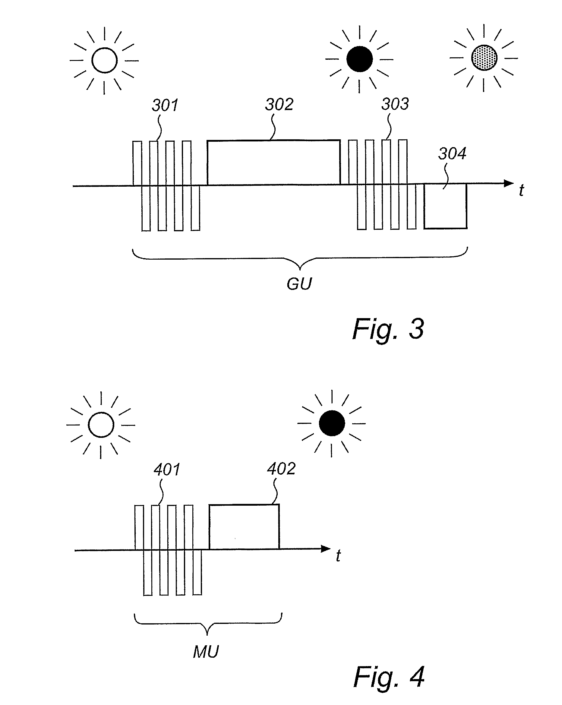
[0055] A second method to enable the GU to MU transition is to write the first monochrome image of the MU series using the GU waveform. This has the advantage that all gray pixels are made either black or white according to the well defined GU waveforms, and therefore no additional artefacts will be introduced. Of course, the image update time will be longer than in MU mode (but shorter than in GU as there will be no transitions from e.g. white to dark grey or black to light grey—these are generally the longest waveforms).

[0056] Once all pixels are in the black or white state, image update can proceed according to the shorter MU waveforms.

[0057] This embodiment is thus recognized in that swithing from the grayscale updating mode to the monochrome updating mode is always accompanied by the use of the grayscale drive signal that puts the pixel into either of its extreme states.

[0058] This approach will remove the problems of i...

embodiment 3

Transition with Addition of a DC Voltage Pulse to the First MU Waveform

[0059] A third method to enable the GU to MU transition is to incorporate additional voltage pulses to the MU waveforms of the first monochrome image of the MU series in order to remove the DC voltage induced in the final image of the GU sequence.

[0060] This can be achieved for example for the waveform shown in FIG. 7, where a transition from a dark grey pixel (from the last GU waveform) to a white pixel (in the first MU waveform) is rendered. In this embodiment, for a 4 grey level display, 16 additional waveforms could be stored in a separate look-up-table (for example called MU′) to facilitate this transition.

[0061] Now, the voltage used to write in the dark grey pixel in the GU image is removed by the short voltage pulse prior to the normal MU waveform. This approach will remove the problems of image retention and will reduce the DC balancing problem described above using a drive waveform which is shorter t...


PUM


Abstract

The present inventions relates to electrophoretic displays that are switchable between a grayscale updating mode (502) and a monochrome updating mode (501). The monochrome updating mode (501) provides for extreme pixel states only (e.g. black and white), whereas the grayscale updating mode (501) provides for intermediate grayscale pixels states as well. According to the present invention, a suitably selected transition signal (504) is applied when switching from the grayscale updating mode (502) to the monochrome updating mode (501). The transition signal (504) involves a drive pulse that serves to reduce the level of remnant DC voltage otherwise occurring in each pixel due to differences in the grayscale updating mode (502) and the monochrome updating mode (501).

Description

FIELD OF THE INVENTION [0001] The present invention relates to an electrophoretic display, and in particular to such a display that provides for transitions between a grayscale drive scheme and a monochrome drive scheme. TECHNOLOGICAL BACKGROUND [0002] Electrophoretic displays are known since long, for example from U.S. Pat. No. 3,612,758. The fundamental principle of electrophoretic displays is that the appearance of an electrophoretic media encapsulated in the display is controllable by means of electrical fields. To this end the electrophoretic media typically comprises electrically charged particles having a first optical appearance (e.g. black) contained in a fluid such as liquid or air having a second optical appearance (e.g. white) different from the first optical appearance. Alternatively the media might be transparent and comprise two different type of particles having different colors and opposite charge. [0003] The display typically comprises a plurality of pixels, each p...

Claims


Application Information

Patent Timeline
IPC IPC(8): G09G3/34G09G5/02G09G5/34
CPCG09G3/344G09G5/028G09G2310/0245G09G2320/0204G09G2340/0428
Inventor JOHNSON, MARK THOMASZHOU, GUOFUVAN DE KAMER, JOHANNES PETRUS
Owner INTERTRUST TECH CORP
Why Eureka
Try Eureka