Addressable brush contact array

Inactive Publication Date: 2007-06-28
XEROX CORP
View PDF7 Cites 7 Cited by
  • Summary
  • Abstract
  • Description
  • Claims
  • Application Information

AI Technical Summary

Benefits of technology

[0018] Thus, with respect to electronic display applications, there is a need for an addressable brush contact array th

Problems solved by technology

While the zebra connector exhibits desirable properties for a contact array and has been successfully used for 100 dpi printing demonstrations, for example, there are several factors that make them unsuitable for some commercial applications.
While at first glance this would seem adequate for a 300 dpi printer, such zebra connectors will only work for printing in the 100 dpi range.
The primary reason for the resolution limitation is that the zebra connectors must rely on redundant contact to work predictably.
This is because the trace width and pitch is not well controlled in the manufacturing process, with tolerances being as large as 50% of nominal values.
If the system is not properly designed, zebra traces, conductive islands, and driver pads can be electrically shorted together, resulting in blurring of the image, moiré patterns, and damage t

Method used


Image

  • Addressable brush contact array
  • Addressable brush contact array
  • Addressable brush contact array

Examples


Embodiment Construction

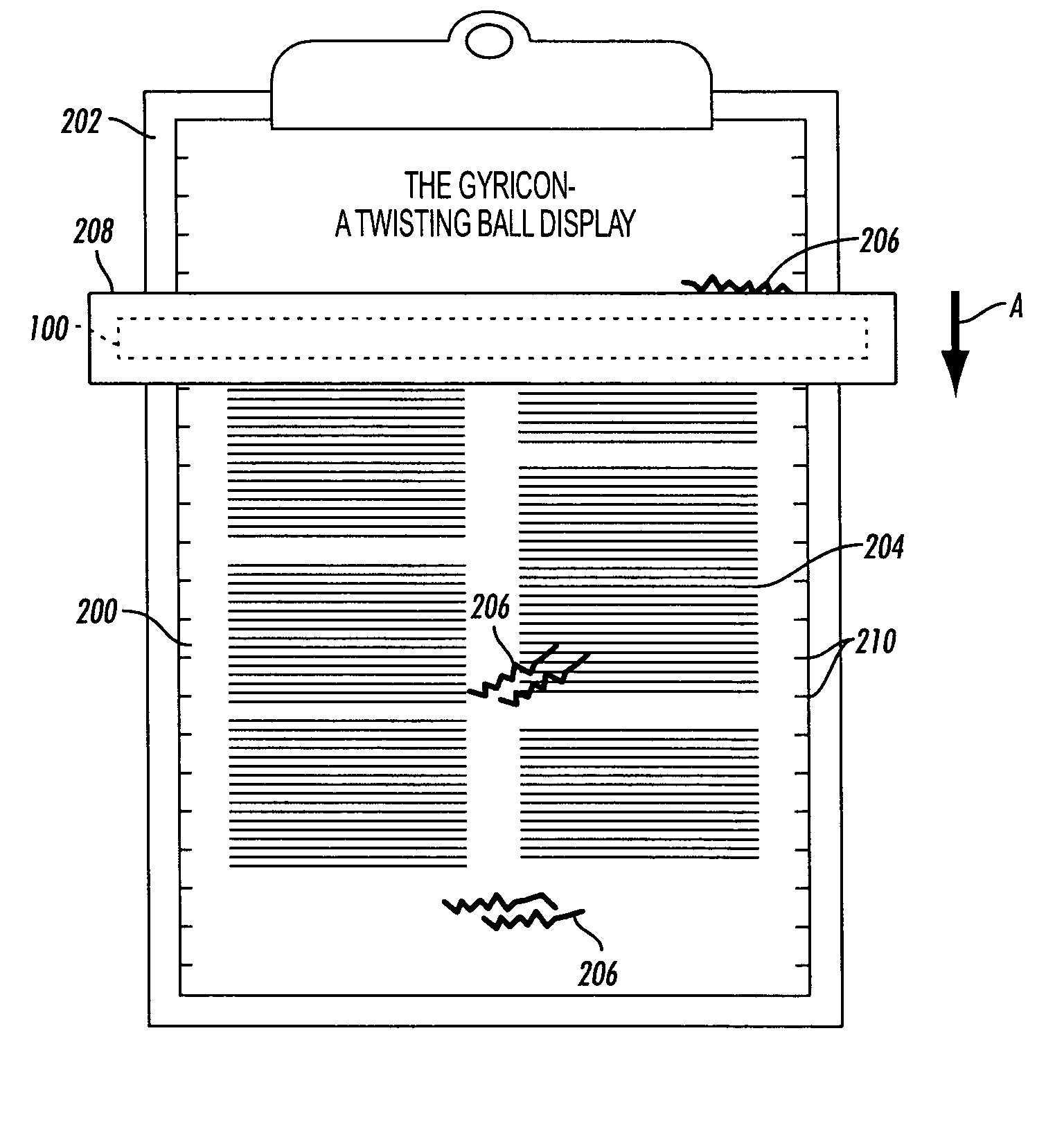
[0031] The addressable brush contact array described herein involves the use of oriented conductive fibers attached to addressing electrodes to transfer imagewise charge to or from an array of individual electrodes on a two-dimensional surface (The charge retention electrodes). The two-dimensional surface can be the writing surface of an electronic paper display or the drum of a xerographic printer.

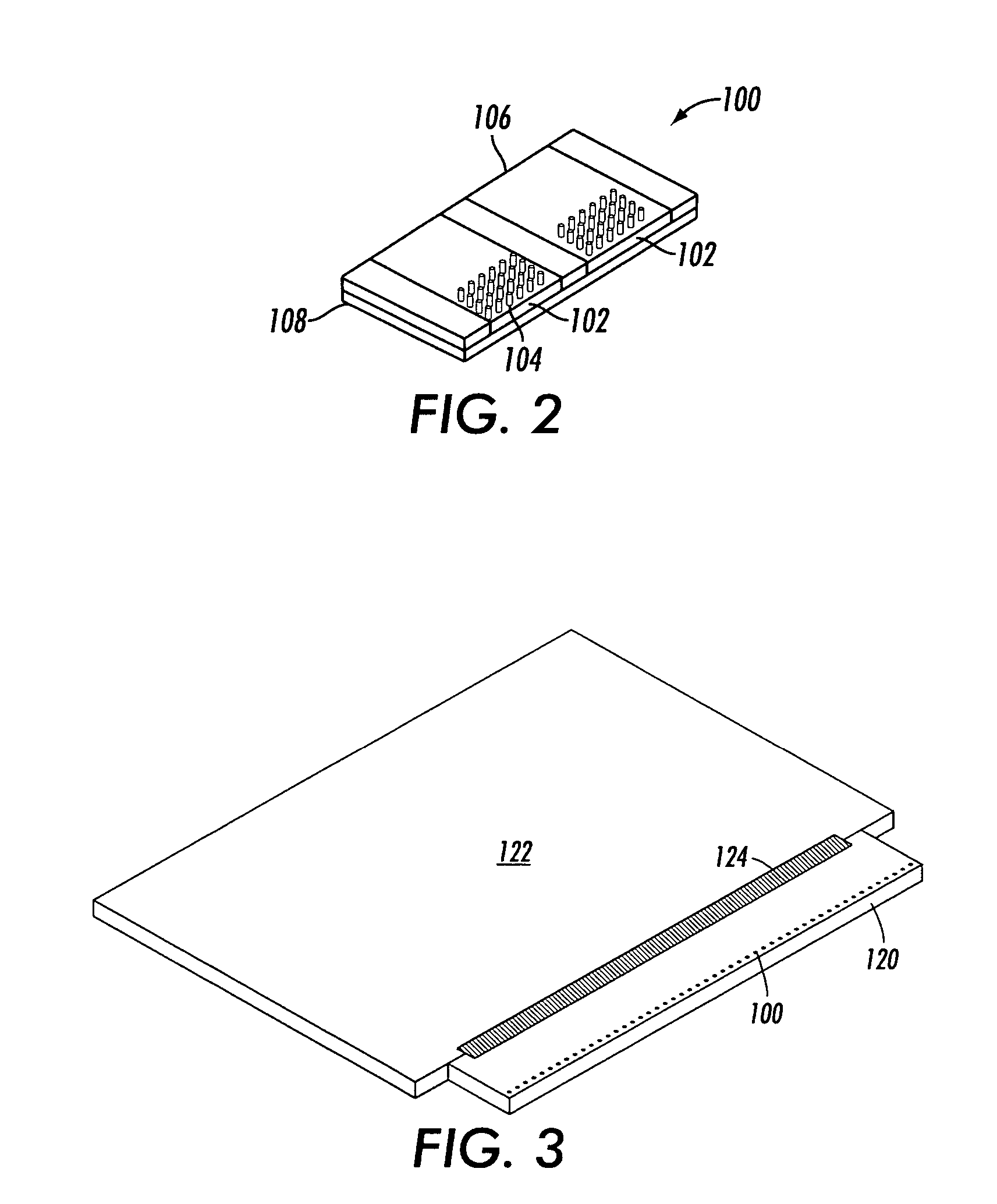
[0032] With reference now to FIG. 2, an addressable brush contact array 100 is shown. The array 100 comprises one or more linear rows 102 of addressing electrodes that can be mounted on a narrow wand or addressing bar (not shown). If there is more than one row of electrodes, then the electrodes of each row would be staggered with respect to the electrodes of adjacent rows to enable a high fill of charge transfer without creating fabrication problems by spacing the fibers too close on adjacent electrodes.

[0033] Thus, the brush contact array 100 may be thought of as a brush made with rows...


PUM


Abstract

An addressable brush contact array comprising oriented conductive fibers attached to addressing electrodes to transfer imagewise charge to or from an array of individual electrodes on a two dimensional surface. The two dimensional surface receiving this charge can be, for example, the writing surface of an electronic paper display or the drum of a xerographic printer. The addressing electrodes generally consist of one or more linear rows of electrodes on a narrow wand or addressing bar. More than one row of electrodes the electrodes of each row may be staggered with respect to the electrodes of adjacent rows to enable a high fill of charge transfer without creating fabrication problems by spacing the fibers too close on adjacent electrodes.

Description

BACKGROUND [0001] This exemplary embodiment relates to the use of electronic display components for electric paper applications. The exemplary embodiment is designed for use with Gyricon electric paper but may also be used with electric paper based on liquid crystal, electrophoretic, and other field-effect display technologies as well as other applications. [0002] Electric reusable paper (or EP) can be defined as any electronically-addressable display medium that approximates paper in form and function. Electric reusable paper should be light-weight, thin, and flexible, and it should display images indefinitely while consuming little or no power. In addition, electric reusable paper should be re-usable. One must be able to erase images and create new ones repeatedly. Preferably, electric reusable paper should display images using reflected light and allow a very wide-viewing angle. [0003] One way to make electric reusable paper possible using traditional electronic display technolog...

Claims


Application Information

Patent Timeline
IPC IPC(8): G09G3/34
CPCG02B26/004G02B26/026
Inventor HOWARD, MATTHEW E.SHERIDON, NICHOLAS K.
Owner XEROX CORP
Why Eureka
Try Eureka