Eureka AIR delivers breakthrough ideas for toughest innovation challenges, trusted by R&D personnel around the world.

Method for revising wafer transferring device of milling equipment

A technology of transmission device and calibration method, which is applied in the direction of grinding device, grinding/polishing equipment, grinding machine tool, etc., can solve the problems of large aiming error, inconvenient observation, and inaccurateness, and achieve easy observation, improved alignment accuracy, and accurate The effect of convenient adjustment

Inactive Publication Date: 2008-07-09
HEJIAN TECH SUZHOU
View PDF1 Cites 2 Cited by
  • Summary
  • Abstract
  • Description
  • Claims
  • Application Information

AI Technical Summary

Problems solved by technology

In the past, when correcting the pick-up position of the conveying device, the method of visual observation was used to check whether the center of the wafer coincides with the center of the conveying device. However, this detection is very inconvenient for observation, and the aiming error is large and not accurate enough.

Method used


Image

  • Method for revising wafer transferring device of milling equipment
  • Method for revising wafer transferring device of milling equipment
  • Method for revising wafer transferring device of milling equipment

Examples


Embodiment Construction

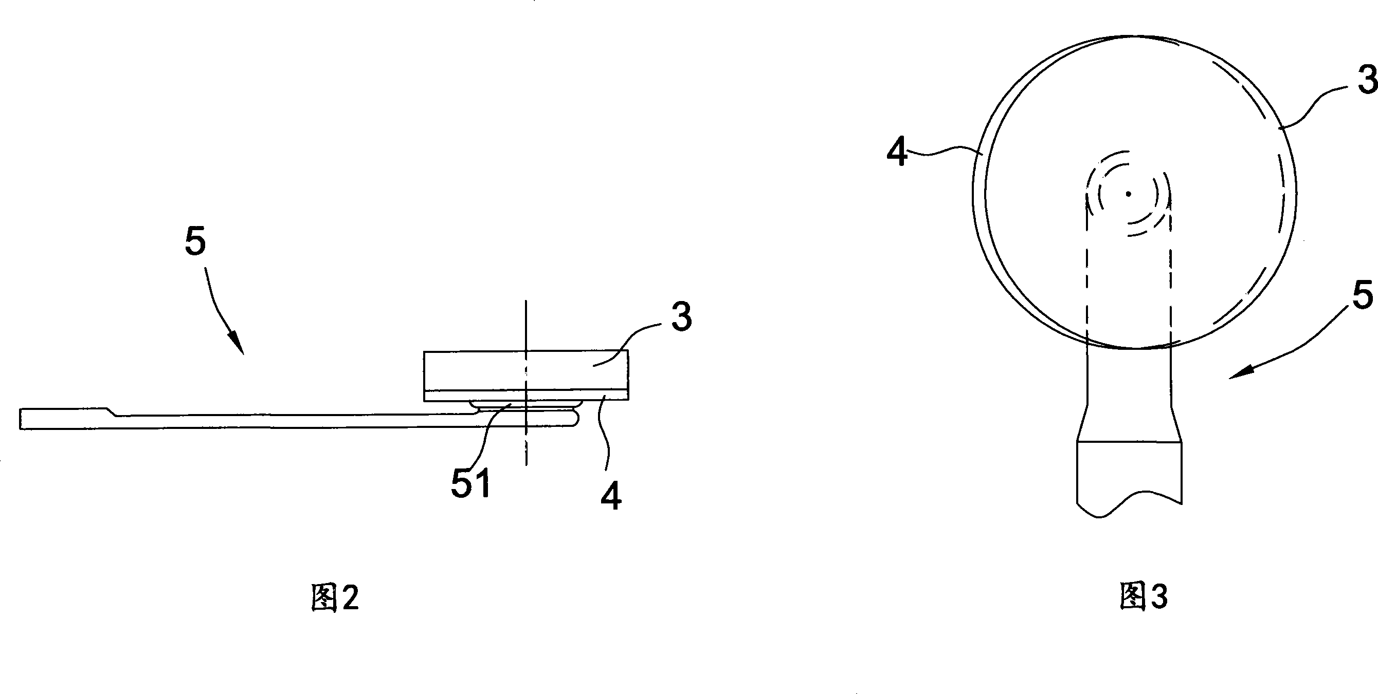
[0021] Referring to accompanying drawings 2 to 3, a method for calibrating a wafer conveying device of a grinding equipment is used to periodically verify the pick-up position of the conveying device of a chemical-mechanical grinder. The conveying device described here usually refers to It is a manipulator, and the front end of the manipulator has a vacuum nozzle for absorbing wafers (the left side is "rear" in the accompanying drawing 2, and the right side is "front").

[0022] The calibration method of the wafer transfer device of the grinding equipment includes the following steps:

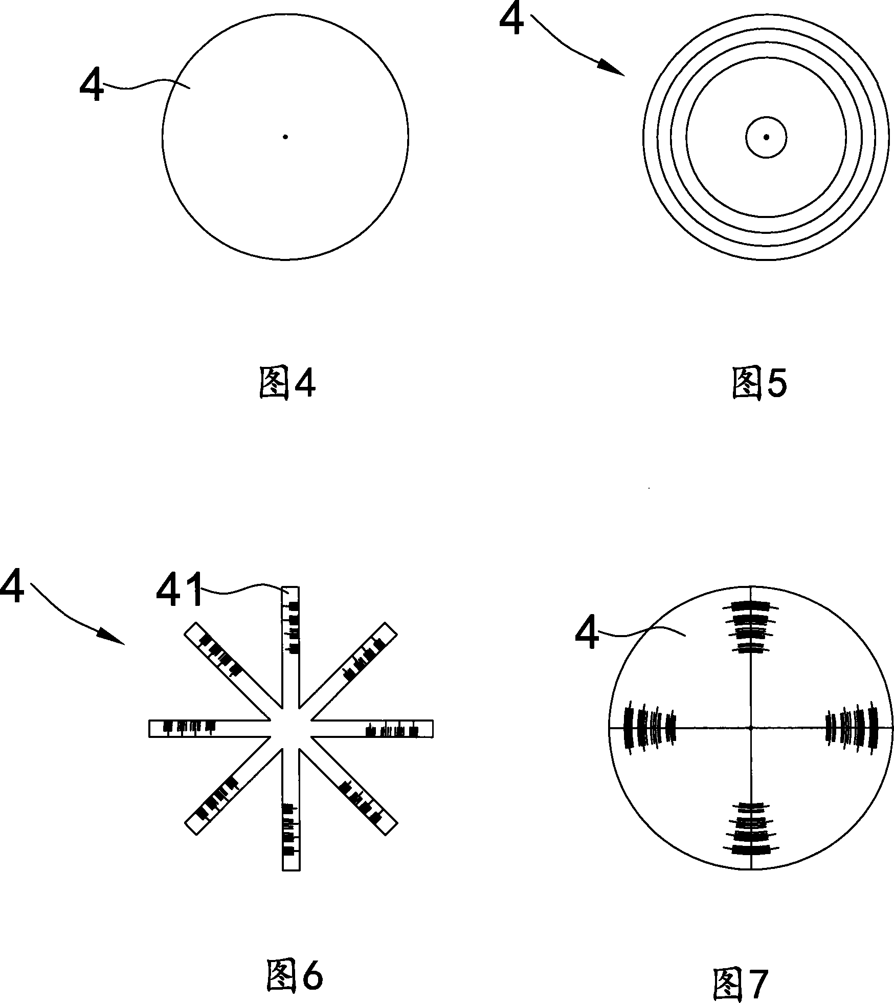
[0023] a, the correction sheet 4 whose outer diameter is greater than or equal to the outer diameter of the wafer 3 to be processed is set on the transfer device 5, the front end of the transfer device 5 has a support part 51 for carrying the wafer, and the support part 51 has a vacuum suction mouth, align the center of the correction sheet 4 with the center of the support part 51, and fix the ...


PUM


Abstract

A correction method of the wafer conveyer of a grinder includes three steps: (a) a correction plate (4) with an outer diameter larger than or equal to the outer diameter of a wafer (3) waiting to be processed is arranged on the conveyer (5), which is provided with a supporting part (51) used to bear the wafer, and the center of the correction plate is aligned with the center of the supporting part; (b) the supporting part is extended into the bottom of a wafer-bearing box and bears the wafer waiting to be processed, which is placed on the upper side of the correction plate; (c) the position relation between the edge of the wafer and the correction plate is compared in order to accurately regulate the grinder. Utilizing the comparison between the edge of the wafer and the correction plate, the present invention not only is simple and convenient for observation but also can improve the accuracy of correction and easily obtain the offset distance of the center of the supporting part, so that the wafer conveyer can be accurately and rapidly regulated.

Description

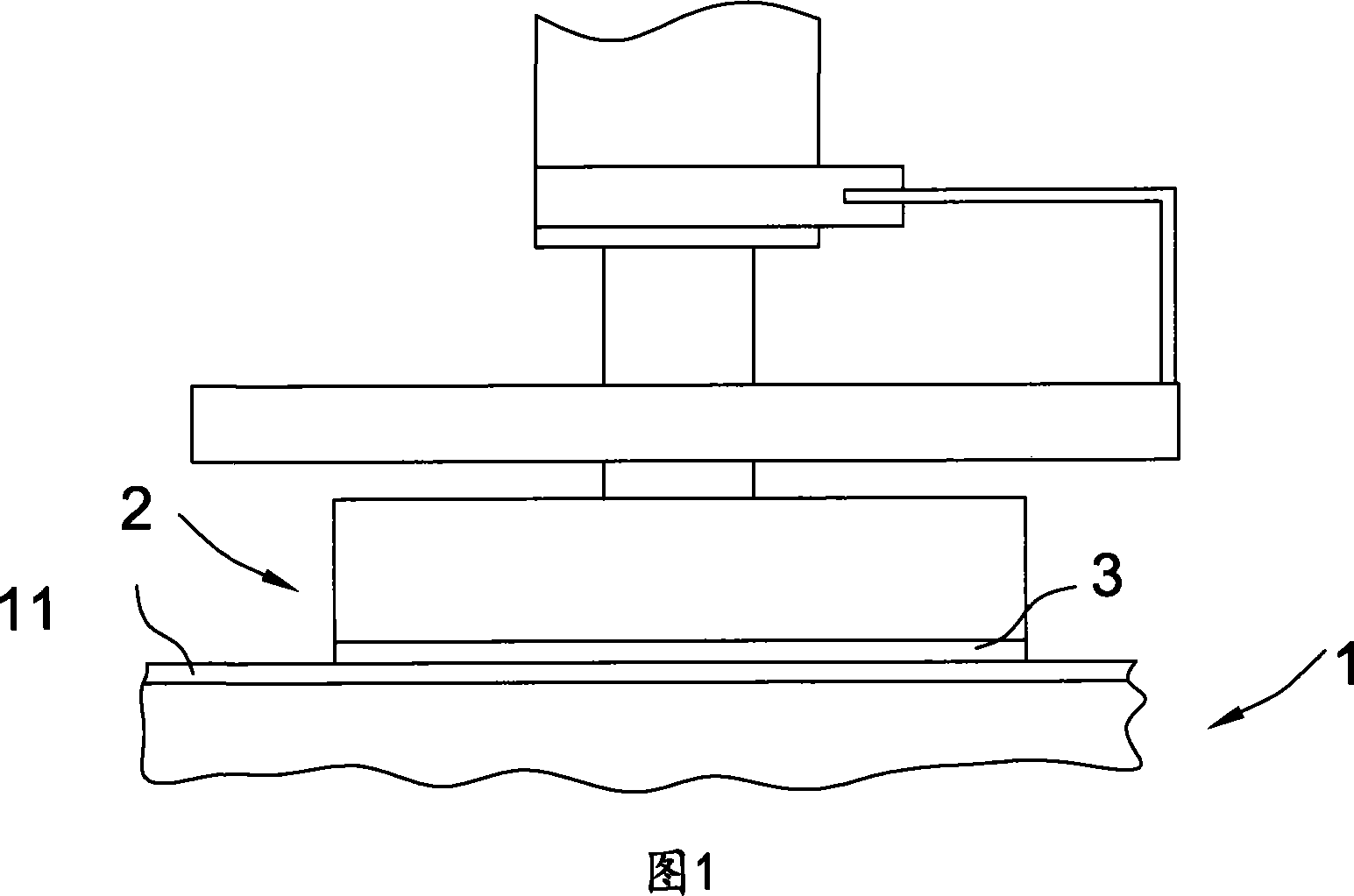
technical field [0001] The invention belongs to the field of wafer material grinding and processing, in particular to a calibration method for a wafer transfer device of a chemical-mechanical grinding machine. Background technique [0002] semiconductor wafers for the construction of optical, electronic or optoelectronic components, requiring the use of techniques for transferring and bonding directly the layers of the first wafer forming the source base to the second wafer forming the support, prior to forming an integrated circuit, Due to the high technical requirements of direct bonding and the strict requirements on the smoothness of the bonding surface, it is necessary to improve the surface finish of the wafer through grinding. [0003] Referring to accompanying drawing 1, the known chemical-mechanical grinding machine in the prior art comprises: grinding turntable 1, grinding head 2, wherein the surface of turntable 1 is covered with polishing cloth 11, and grinding h...

Claims


Application Information

Patent Timeline
Patent Type & Authority Applications(China)
IPC IPC(8): B24B29/00B24B37/04H01L21/304B24B37/34
Inventor 陈立轩曹斌刘长安
Owner HEJIAN TECH SUZHOU
Why Eureka
Eureka Blog
Learn More