
Photographing apparatus, image display method, computer program and storage medium

a technology of image display and photography apparatus, applied in the field of photography apparatus, image display method, computer program and storage medium, can solve the problems of difficult to dispose of cameras in such a manner, coincident points on the object side, and physical size of each camera, so as to reduce the parallax of a plurality of photographed images

Inactive Publication Date: 2007-06-28
CANON KK
View PDF6 Cites 62 Cited by
  • Summary
  • Abstract
  • Description
  • Claims
  • Application Information

AI Technical Summary

Benefits of technology

[0021] The present invention solves the above-described problems and aims to provide a photographing apparatus capable of making compact a photographing unit and reducing a parallax of a plurality of photographed images, an image display method, a computer program and a storage medium.

Problems solved by technology

However, in practice, each camera has a physical size and is interfered with each other.
It is therefore difficult to dispose the cameras in such a manner that the principal points on the object side become coincident.
It is therefore difficult to join the two images smoothly.
Therefore, the base line length L becomes long, a parallax difference between images taken with adjacent cameras becomes large, and it is difficult to connect the images at the joining portion without suppressing contradiction.
Since the front ends of the cameras are made radially open, the camera lens layout becomes conspicuous and it is difficult to make compact the whole housing of a camera.
Therefore, the pixel density of an image after conversion is not uniform over the whole area so that a portion greatly enlarged has coarse pixels and its image quality is degraded.
Such needs cannot be satisfied by a hyperbolic mirror system.

Method used


Image

  • Photographing apparatus, image display method, computer program and storage medium
  • Photographing apparatus, image display method, computer program and storage medium
  • Photographing apparatus, image display method, computer program and storage medium

Examples


first embodiment

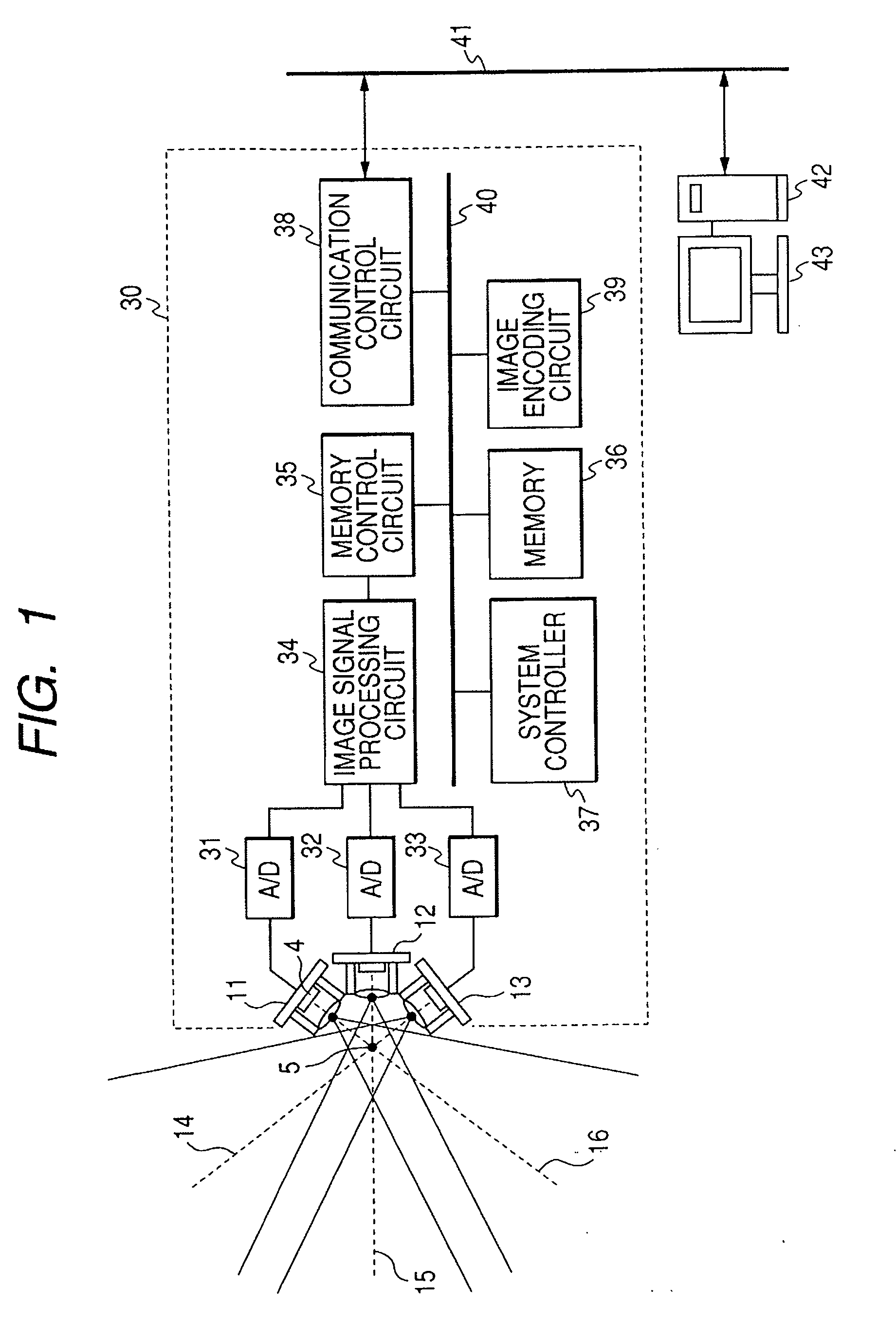
[0041]FIG. 1 is a block diagram showing the outline structure of a wide-angle photographing apparatus according to an embodiment of the present invention. In FIG. 1, a housing 30 of the wide-angle photographing apparatus accommodates cameras 11, 12 and 13 each constituted of a lens and an image pickup device, and a camera drive control circuit. Each of the cameras 11, 12 and 13 uses a single focus lens, and optical axes 14, 15 and 16 of the cameras are disposed in such a manner that the optical axes cross at a cross point of each lens on an object side.

[0042] A lens capable of being in-focus from a near field to a far field through pan focussing may be used for the camera. Alternatively a lens capable of being automatically set in-focus through auto focussing may be used. In this case, if focusses of three cameras are different, focus points of images of a panorama display are different and the images are difficult to be clearly observed. Therefore, one camera which mainly photogra...

second embodiment

[0069]FIG. 7 is an illustrative diagram of a camera layout according to the second embodiment of the present invention. In the first embodiment, although the cameras are disposed along the horizontal direction, in the second embodiments cameras 71 are disposed along both the horizontal and vertical directions in such a manner that the optical axes of the cameras cross at one cross point 5 on the object side.

[0070]FIG. 8A is a front view of the second embodiment in which the cameras 71 are disposed in a matrix form. FIG. 8B is a cross sectional view taken along line 8C-8C in FIG. 8A and FIG. 8B is a cross sectional view taken along line 8B-8B in FIG. 8A. In the 8C-8C cross sectional view of FIG. 8B, the optical axes of the cameras cross at the cross point 5, and the photographing field angle along the horizontal direction is in the range indicated by an arrow 75. In the 8B-8B cross sectional view of FIG. 8C, the optical axes of the cameras cross at the cross point 5, and the photogr...

third embodiment

[0073]FIG. 9 is an illustrative diagram of the third embodiment of the present invention. If the wide-angle photographing apparatus is used for monitoring, it is necessary to photograph an object having a low illuminance, such as in the night. Generally, a camera using image pickup devices such as CCD photographs an object by setting an infrared cut filter just above the image pickup device in the day, and not by setting the infrared cut filer in a low illuminance.

[0074] In the wide-angle photographing apparatus of the third embodiment, mounted in a housing 83 are cameras 11 and 12 disposed in such a manner that the optical axes cross at a cross point 5 similar to the first embodiment. An opening 80 for camera lenses is formed through the housing 83, and an infrared cut filter substrate 81 is supported inside the housing to be slidable relative to the opening by an unrepresented drive mechanism. For example, the drive mechanism may have the structure that a movable member for holdi...


PUM


Abstract

A photographing apparatus comprises a plurality of optical image pickup units which converges object light and forming an optical image on a focus plane of an image pickup device and an image forming unit which forms a plurality of photographed images from optical images formed by the optical image pickup units. The optical axes of the optical image pickup units cross at one point near lenses, the optical image pickup units are disposed at an equal distance from the cross point, and the optical axes are set at a predetermined angle in such a manner that photographing fields of adjacent optical image pickup units are made contiguous with each other.

Description

BACKGROUND OF THE INVENTION [0001] 1. Field of the Invention [0002] The present invention relates to technologies for acquiring a photographed image in a wide range by using a photographing apparatus. [0003] 2. Related Background Art [0004] A wide-angle photographing apparatus is known which can acquire a photographed image in a wide range by combining photographed images taken with a plurality of optical photographic systems. For example, this wide-angle photographing apparatus is applied to a monitor camera, a television conference camera and the like. [0005] For a wide range photographing system, a method has been proposed by which a plurality of cameras are disposed radially as shown in FIG. 10 and photographed images taken with the cameras are joined together to realize paronama photographing. A camera 1 is disposed on each side of a polygonal housing 101 to photograph each divided area of a photographing range of 360°. The system of this kind is disclosed, for example, in Japa...

Claims


Application Information

Patent Timeline
Patent Type & Authority Applications(United States)
IPC IPC(8): G02B13/16
CPCG03B37/04
Inventor NOSE, HIROYASU
Owner CANON KK
Learn More